Download

1 / 44
470 likes | 602 Vues

E N D
Experimental and Micromechanical Computational Study of Pile Foundations Subjected to Liquefaction-Induced Lateral SpreadingS. Thevanayagam, UBResearch Kickoff MeetingNov. 19, 2005, RPIPI – R. Dobry, co-PI’s: A. Elgamal, S. Thevanayagam, T. Abdoun, M. ZeghalAcknowledgements: Kanagalingam, N. Ecemis
Outline • Introduction a. UB 1-g Tests b. Schedule • Laminar Box Strong Floor-Shaking a. Preparations, Progress & Schedule b. Strong Floor, Actuators, Shaking, Logistics, Safety • Sand Construction – Plans & progress a. Sand Hydraulic Filling – Preparations and progress b. Dry runs – Preparations & fine tuning equipment c. Sand CPT Testing – plans • Year-1 Test Plans & Schedule a. Tests & Instrumentation – preliminary plans b. Coordination & integration b. Data Acquisition & IT (preliminary) • Equipment & Instrumentation - Progress Summary
Pile (Test 1A: High EI pile, Test 1B: Low EI pile) F#55 Sand, Dr~45% 2-D Laminar Box (24 Laminates) 6.2 m Ball Bearings Shaking Frame on Strong Floor a=2 or 3 deg. SECTIONAL VIEW 3.35 m 2.75 m 5.0 m 5.6 m PLAN Task 1: Single Pile (Tests 1 & 2)(shaking in perpendicular directions)
Pile Cap Pile F#55 Sand, Dr~45% 2-D Laminar Box (24 Laminates) 6.2 m Ball Bearings Shaking Frame on Strong Floor a=2 or 3 deg. SECTIONAL VIEW 3.35 m 2.75 m 5.0 m 5.6 m PLAN Task 1: Group Pile (Tests 3 and 4)(shaking in perpendicular directions) • Task 1 Total Tests: 4 • Yr-1: Test #1 • Yr-2: Tests #2 and 3 • Yr-3: Test #4
Modular Multilayer-Laminate-Bearing Design; 5.0x2.75x6.2m (85 cubic meter maximum capacity) Simulate 2-D Ground Response for Soil-Foundation-Structure Interaction Studies at or Near Full Scale 1-g Geotechnical Studies to Compliment Centrifuge 2-D Large Scale Geotechnical Laminar Box - Details
Reaction Wall Strong Floor Fast Actuator (100-200 ton) 2D-Bearings 2-D Laminar Box – Strong Floor - Shaking
Dynamic Actuators& Controllers – For Laminar Box Shaking • 3 x 100 tons Dynamic Actuators (0-100Hz, 1.25 m/sec, 800 gpm valves)
Large Dynamic and Static Actuatorsand Controllers • 3 x 100 tons Dynamic Actuators (0-100Hz) • 2 x 200 tons Static Actuators • Flex-Test Controllers and Software • STS Controller (MTS469) – Custom Made
Reaction Wall Strong Floor Fast Actuator (100-200 ton) 2D-Bearings 2-D Large Scale Geotechnical Laminar Box
Laminar Box – Strong Floor Modification PLAN VIEW
LAB Reaction Wall Diffuser Slurry Pump (5 HP, 3f, 208V, 14.5 A) Laminar Box (LB) 3”/ 350 ft Hose Water Sand Slurry Ottawa F-55 Sand (150 T) Water Strong Floor Circulating Water Pump Sand Container Laminar Box Sand Placement Placement rate / Density – To be worked out Target Density: ~ 30% - 50% Density measurements during placement & CPT measurements after placement
Field Hydraulic Fill Placement Methods & CPT Results Low Speed + Compaction High Speed Bottom Dump
Hydraulic Fill – Field CPT Data(Mitchell et al.) Better Control Possible in the Lab. Environment; Includes plans for development of placement controls to achieve desired density ranges
Hydraulic Filling – Preliminary Pump Tests - completed Slurry Pump (5 HP, 3f, 208V, 14.5 A) Sand Slurry Water Ottawa F-55 Sand Water Container-B Circulating Water Pump Container-A Placement rate & Density Controls – To be worked out Target Density: ~ 30% - 50% Density measurements during placement & CPT measurements after placement
LAB Reaction Wall Diffuser Slurry Pump (5 HP, 3f, 208V, 14.5 A) Laminar Box (LB) 3”/ 350 ft Hose Water Sand Slurry Ottawa F-55 Sand (150 T) Water Strong Floor Circulating Water Pump Sand Container Laminar Box Sand Placement Preparation Tests Placement rate / Density – To be worked out Target Density: ~ 30% - 50% Density measurements during placement & CPT measurements after placement
CPT Testing Additional Sampling & Density measurements 1. Tip 2. Sleeve 3. Pore pressure Cost (TBE) • 100% Soil Saturation – Hydraulic Filling: For Fully Saturated Tests. • Drain water to obtain “Dry” Sand – For Unsaturated or dry Tests
Preparatory • Dry Runs & Preliminary Equipment Tests • Free-Field Liquefaction • Level Ground (LG-1) – Harmonic progressive amplitude increase (May 06) • Sloping Ground (SG-1) - Harmonic progressive amplitude increase (July 06) • Coord Pre-test data for num. modelers – 2mo before tests for Class A prediction & post-test model calibration (March 06 & May 06) • Single Pile • High-EI Pile (Test 1A) – Harmonic 1-2Hz, 0.2-0.3g (Aug. 06) • Low-EI Pile (Test 1B) – Harmonic 1-2Hz, 0.2-0.3g (Oct. 06) • Coordination w/ Centrifuge Tests & IT Year-1 Test Plans (2005-06)
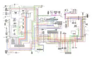
Instrumentation – Schematic Plan view Reaction Wall Actuator Potentiometer MEMS Shape Cable Accelerometer Piezometer Strain Gauge Schematic Diagram – Plan View
Pile (Test 1A: High EI pile, Test 1B: Low EI pile) F#55 Sand, Dr~45% 2-D Laminar Box (24 Laminates) 6.2 m Ball Bearings Shaking Frame on Strong Floor a=2 or 3 deg. SECTIONAL VIEW 3.35 m 2.75 m 5.0 m 5.6 m PLAN Single Pile (Tests 1A & 1B) Boundary “Ring – Corrections” To be worked out
Soil-Pile Instrumentation MEMS Shape Cable Potentiometer Accelerometer Piezometer Strain Gauge Schematic Diagram- Sectional Views
Soil-Pile Instrumentation Reaction Wall Actuator Potentiometer MEMS Shape Cable Accelerometer Piezometer Strain Gauge Schematic Diagram – Plan View
KRYPTON Soil-Pile Instrumentation
Pile Cap Pile F#55 Sand, Dr~45% 2-D Laminar Box (24 Laminates) 6.2 m Ball Bearings Shaking Frame on Strong Floor a=2 or 3 deg. SECTIONAL VIEW 3.35 m 2.75 m 5.0 m 5.6 m PLAN Group Pile (Test 3; Yr-2)
Instrumentation Summary Soil Sensors • 34 Accelerometers – Rings • 28 Accelerometers – Soil • 54 Piezometers – Soil • 40 Potentiometers – Rings • 3 MEMS Shape Cables – Soil • Krypton Imager – Field of View: Top Surface and Top 2m Rings Pile Sensors • Many Strain gauges • 2 MEMS Shape Cables • Krypton Imager - Field of View: Pile Cap Others • Instrument Mounting Frame - Available • Pacific Data Acquisition System (285 Channels; 256 available) • Krypton (30) – 50 Available • MEMS (144) - ?? Available • Time stamp, Data Synchronization & IT – Need to develop (Jason)
Task 1 Progress Summary • Introduction a. UB 1-g Tests – Task 1 b. Schedule • Laminar Box Strong Floor-Shaking – Laminar box Completed; Shaking Design completed; Strong floor-box interface Fabrication & Testing planned a. Preparations, Progress & Schedule b. Strong Floor, Actuators, Shaking, Logistics, Safety • Sand Construction – Plans & progress – Pump tests completed a. Sand Hydraulic Filling & Density Control – Preparations and progress b. Dry runs – Preparations & fine tuning equipment c. Sand CPT Testing – plans • Year-1 Test Plans & Schedule – NEES Lab Scheduled (Typ 10wks/test) a. Tests & Instrumentation – prelim. plans & Budget completed (w/ AMR) b. Coordination & integration (with Other Tasks) b. Data Acquisition & IT (preliminary) • Equipment & Instrumentation - Progress Summary