Download
1 / 19
190 likes | 213 Vues
A comprehensive guide on fuel-air modeling of internal combustion engine cycles, covering combustion strategies, emission norms, and thermodynamic modeling for efficient combustion processes.

E N D
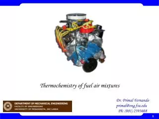
Fuel-Air Modeling of IC Engine Cycles P M V Subbarao Professor Mechanical Engineering Department State of the Art Modeling of Artificial Horses.….
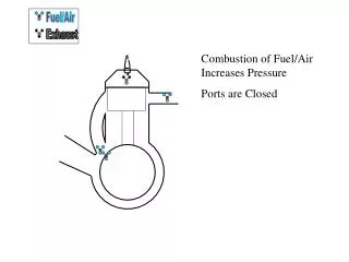
Engineering Strategy to Utilize A Resource • Engineering constraint: Both combustion and expansion have to be finished in a single stroke. • Rapid combustion : Constant Volume combustion • Less time to combustion process. • More time to adiabatic expansion • Slow combustion : Constant pressure combustion • More time to combustion process. • Less time to adiabatic expansion
Emission norms for Heavy diesel vehicles: A move to Bharat Stage IV+ from 2016, before moving to Bharat Stage V in 2021
Second law limit on possible extent of reaction • Reactants Products • At any instant during the combustion process, a cylinder contains a combination of reactants and products. • A reaction seizes when the entropy of an adiabatic reactor reaches its maximum value. • The value of maximum entropy will vary with the pressure and temperature of the reaction. • A reaction system and parameters of reaction should be designed such that the maximum entropy is obtained when the reaction is almost complete (>98%??).
Generalized Theory of Extent of Reaction Possible p1,T1 p2,T2 Entropy of Universe p3,T3 Extent of Reaction
Mathematical Model for Culmination of Reaction Possible extent of reaction: For every fuel, a designer should know all possible reactants !!! Some products will influence the efficiency of reaction. Few other may not influence the efficiency of reaction but severely affect the environment. The optimal parameters for efficient reaction may not be optimal for safe reaction !! There may be a need to use secondary reactor with catalysts. Catalytic Converter
Closure on Analysis of Combustion Complete & Adiabatic combustion at constant volume Complete & Adiabatic combustion at constant pressure Design of sub-systems for better combustion needs more detailed analysis of thermo-physical & thermo chemical processes preceding and during combustion.
3—4 Isentropic expansion of the burned gases For a infinitesimal expansion process: Using first order models for properties:
4—5 Ideal adiabatic blow down Sudden Exhaust :
More Realistic Exhaust blow down • Late in power cycle exhaust valve is opened • Pressure differential pushes hot exhaust gas out of cylinder and through exhaust system. • The mass blow down process, which occurs between EVO and BDC (180 CA), is to be thermodynamically designed to enhance the predictive capability of the cyclic integral. • An empirical correlation for the blow down pressure is obtained as in the following form:
Nature of Blowdown • After EVO, the mass in cylinder decreases sharply as gas blowdown occurs due to the significant pressure difference across the exhaust valve. • In most of the cases, 20% -- 50% of the exhaust gas exits the exhaust valve during the blowdown process. • During the exhaust stroke, the piston moves towards TDC, which further pushes the mass of gases in cylinder to leave the engine. • At 720o CA, the mass of gases residing in the clearance volume, which is termed as the residual gas, will be mixed with the fresh intake charge in the subsequent cycle
Empirical Relations for Pressure during blowdown where and m =0.45 is the shape factor determined by experimental correlation.
Intake Conditions • The residual mass fraction (f ), a parameter which is crucial in the determination of the charge air/gas temperature at IVC (Ti). • This is estimated from the previous cycle. Hence, the residual mass fraction can be estimated by