Lead-free for passive components
Lead-free for passive components. 向性一 資源工程學系 Email: hsingi@mail.ncku.edu.tw Tel:06-2757575 ext 62821. WEEE -Waste Electrical and Electronic Equipment.

Lead-free for passive components
E N D
Presentation Transcript
Lead-free for passive components 向性一 資源工程學系 Email: hsingi@mail.ncku.edu.tw Tel:06-2757575 ext 62821
WEEE -Waste Electrical and Electronic Equipment • The WEEE Directive is primarily tasked with reducing the amount of electrical and electronic equipment (often expressed as EEE) from entering landfill at the end of its useful life by encouraging reuse, recycling and separate collection. It is apparent from this statement that the WEEE directive will not eradicate all EEE from landfill. • The role of RoHS is to reduce harmful substances [materials] at source, ensuring that these hazardous substances are not leached into the environment by equipment which inevitably fails to be recycled. The WEEE Directive is a separate piece of environmental legislation, though it is directly linked to RoHS.
WEEE -Waste Electrical and Electronic Equipment • RoHS & WEEE directives were instituted by the European Union in 1992 • Similar Legislation: • Japan-Consumer Appliance Law • China's Regulation for Pollution Control of Electronics Products (RPCEP) • USA –State of California
Who is impacted? • Ultimately, anyone who builds, markets or imports electrical or electronic equipment (or components) into the European Union must ensure that the product complies with the RoHS directive, regardless of where it was originally produced.
Who is exempt from RoHS? • Military, Aerospace and network infrastructure equipment for switching, signaling, transmission as well as network management for telecommunication; Pb (lead) used in Servers, Storage and Storage array systems [exemption granted until 2010].... It should be recognized that existing exemptions may be short lived, and should not be relied upon as part of your overall conversion strategy • Influencers to reconsider taking exemption: • Reduction in available markets • Competitive position • Legacy (Sn-Pb) component availability & potential unit price premium
When does WEEE and RoHS take effect? • WEEE = August 13, 2005 • RoHS = 1 July 2006 • Japan: end of 2001 recommended • USA: not defined yet MIL: 3% lead required
Base Material Suppliers, Component Base Material Suppliers, ComponentManufacturers and OEM’s
What is it’s impact on companies designing and building electronic PCB assemblies? ... • [Materials] • −Assurance of RoHS compliance • −Material identification and control • −Supplier confirmation of RoHS compliance
Restriction on Hazardous Substances • RoHS: EU Member States shall ensure that, from 1 July 2006, new electrical and electronic equipment put on the market meets the maximum concentration values on the below six materials: • 1.Lead(Pb) • 2.Mercury (Hg) • 3.Cadmium (Cd) • 4.Hexavalent Chromium (CrVl) • 5.Polybrominated biphenyls (PBB) [Flame retardant used in plastics] • 6.Polybrominateddiphenyl ethers (PBDE) [Flame retardant used in plastics]
WHY LEAD? • Water pollutant • Harmful effects on health (Studies for Pb-Free Gas) • Impacts central nervous system • Encephalopathy & irreversible brain damage • Hematological (anemia), gastrointestinal (colic), kidney, thyroid • Childrens’ IQ scores falling • Implicated in many types of cancer • EPA classified Probable Human Carcinogen Class B2 • Symptoms of Pb poisoning noted at levels as low as 10 mg/dL (infants) and 30 mg/dL (adults)
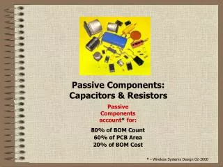
Why Solder? • Despite the fact that the lead consumption in electronics is 0.5% only, the construction of electronic devices and the difficulty of their recycling makes this segment a concern.
Will Additional Substances be added to RoHS? • …when additional scientific evidence is presented, the ‘banned’ substances may increase to encompass other hazardous materials…
What is the difference between lead-free and RoHS compliant? • While lead (Pb) is the most widely used RoHS specific hazardous substance in electrical and electronic equipment (EEE), the term "lead-free" is often wrongly adopted to refer to all of the substances specified in the Restriction of Hazardous Substances (RoHS) Directive. However, RoHS restricts a total of six substances -lead, mercury, cadmium, hexavalent chromium, PBB and PBDE. To be truly “RoHS compliant” with the WEEE –RoHS legislation, the presence of each of these substances must be reduced below their proposed maximum concentration values (MCV)..
Homogeneous materials • Homogeneous materials are defined as materials that cannot be mechanically disjointed into different materials and are “of uniform composition throughout”. Types include: plastics, ceramics, glass, metals, alloys, paper, resins, and coatings
What methods are commonly utilized to assuring supplier compliance? • Survey: Questionnairs • Supplier Documentation • RoHS compliance statements • Material declaration statements (MDS) • Green statement • Inductively Coupled Plasma Testing: typically performed by third party test Lab,
RoHS is very explicit about which substances should be restricted and the precise levels that may be tolerated. Some exceptions are allowed… Appendix Exception #5. Lead in glass of cathode ray tubes, electronic components and fluorescent tubes. For clarity, this exemption applies to lead in the glass parts of cathode ray tubes, lead in the glass parts of electronic components and lead in the glass parts of fluorescent tubes. Electronic components in the context of this exemption could also include glass parts when they are part of an electronic component or electrical and electronic equipment. Example: Trace levels of Pb found in Glass Overcoats, Glass Frit, Inks, etc.
Lead-free program • A. RESEARCH TERMINATION MATERIALS • B. KEY CUSTOMERS INPUTS • C. CURRENT PRODUCTS ANALYSIS • HIGHER REFLOW TEMPERATURE STABILITY • COMPATIBILITY WITH DIFFERENT TYPES OF SOLDER PASTES • ADJUSTMENT OF PLATING PROCESS WITH LEADFRAME SUPPLIERS • D. EVALUATION OF DIFFERENT TYPES OF SOLDER PASTES • LEAD FREE PRODUCT TESTING, RELIABILITY TESTS. • COMPATIBILITY WITH TIN/LEAD SOLDERS • E. CUSTOMER NOTIFICATIONS AND LEADFREE SAMPLES • F. LEAD FREE PRODUCT FOR LEAD FREE ASSEMBLY AND COMPLETE DATA PACKAGE • G. FULL PRODUCTION OF LEAD FREE PARTS
RoHS compliance impacts all components suppliers that provide Tin-Lead (Sn-Pb) finish components. Most component suppliers will need to transition away from Tin-Lead (Sn-Pb) finish components to Lead–Free (Pb-free) alternate.
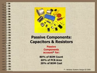
Exemption from Lead Free • Capacitors : High-CV NPO Dielectric Material • Piezo products : • Piezo electronic ceramic elements • Glass frit in fired silver • Resistors : • Resistor material, • Glass frit in fired electrode • First Cover glass • EMI, Trimmers : Dielectric ceramic body • Circuit board : Thick film substrate • Hybrids & Modules : Mounted parts such as above products • Exemption
The Impact of Lead-Free Solders on Ceramic Substrate, Hybrid Microcircuit Assemblies • The reliability of ceramic substrate, hybrid microcircuit (HMC) assemblies will be potentially impacted by the introduction of Pb-free solders as replacements for the traditional Sn-Pb or In-Pb alloys. Those effects can be categorized with respect to • thick film and thin film conductor reliability • the ceramic substrate reliability.
The Impact of Lead-Free Solders on Ceramic Substrate, Hybrid Microcircuit Assemblies • The effect of Pb-free solders on the reliability of the thick film conductor traces and pads can be generalized for all thick film compositions, be they Ag, Ag-Pt, Ag-Pd, Au, Au-Pt, Au-Pd, or Au-Pt-Pd.
The Impact of Lead-Free Solders on Ceramic Substrate, Hybrid Microcircuit Assemblies-II • First of all, the higher processing temperatures and higher Sn contents of the Pb-free solders will increase the rate of thick film dissolution during the course of the assembly process. Excessive consumption of the thick film reduces the margin of remaining material that can support subsequent repair/rework activities which are typically required for these high-value assemblies. Also, there is less thick film layer remaining which can accommodate solid-state inter-metallic compound layer growth during the service life of the HMC product (even at room temperature).
The Impact of Lead-Free Solders on Ceramic Substrate, Hybrid Microcircuit Assemblies-III • Excessive interactions between the thick film layer and the Pb-free solder will require that the following actions be considered: • Using existing technology, the processing window with the Pb-free solder will be more limited, both with respect to soldering time and solder temperature. • Additional thick film layers (i.e., multiple print-dry-fire sequences) may be required in order to build up the conductor features as compensation for the added dissolution effects of Pb-free solders. • Barrier layers such as Ni or Cu can be deposited on top of the thick film pattern (e.g., Ni or Cu) provide an alternative means to curtail the loss of thick film by molten solder dissolution and/or solid-state inter-metallic compound layer growth. • New thick film materials will need to be developed to work with the lead free solders without increasing manufacturing costs due to process limitations or increased material usage.
Lead Free Thick Film Materials • The progression of lead free solders introduction naturally leads to the next level of lead free materials. • Recent EU directives and requirements from some Japanese electronics manufacturers restrict the amount of lead (and other heavy metal compounds) in electronic assemblies, not just in the solder. The next step will be to eliminate lead in the thick film materials and in the package materials (LTCC or HTCC). • Lead is incorporated into many thick film pastes for a variety of reasons. It is in glazes and dielectrics to allow them to fire smooth and pore free, it is in conductors to assist in the adhesion to the substrates and it is in resistors to provide electrical properties.
Lead Free Thick Film Materials-II • Elimination of lead from thick film materials requires research into the area of glass chemistry to find suitable replacements. These replacements must perform the same as, or better than existing materials. • Some replacements will be easier than others and current work is ongoing to replace lead containing thick film materials with lead free versions. There are already many successful replacements on the market.
High Permittivity of relaxor • An intuitive crystallographic model (rattling ion model) has been proposed to explain the giant permittivity of these disordered perovskites. • Assuming a rigid ion model, a large "rattling" space is expected for the smaller B ions in the disordered structure because the large B ions prop open the lattice framework. Much less "rattling" space is expected in the ordered arrangement where neighboring atoms collapse systematically around the small B ions.
Dielectric Relaxation • Another significant characteristic of these "relaxor" ferroelectrics is dielectric relaxation (frequency dependence of the permittivity) from which their name is derived. • With increasing frequency, the permittivity in the low-temperature (ferroelectric) phase decreases and the peak temperature near 0°C shifts towards higher temperature; this is contrasted with the behavior of normal ferroelectrics such as BaTiO3, where the peak temperature changes little with the frequency.
High Permittivity of relaxor • When an electric field is applied to a disordered perovskite, the B ions (usually high valence ions) with a large rattling space can shift easily without distorting the oxygen framework. Larger polarization can be expected for unit magnitude of electric field; in other words, larger dielectric constants and larger Curie-Weiss constants should be typical in this case. On the other hand, in ordered perovskites with a very small rattling space, the B ions cannot move easily without distorting the octahedron. A smaller permittivity and a Curie-Weiss constant are expected.
Diffuse Phase Transition • The exact reason why the phase transition is diffuse in the relaxor ferroelectrics has not yet been clarified. We introduce here the "microscopic composition fluctuation" model which is one of the most widely accepted models for the relaxor ferroelectrics. • Within a single Kaenzig region [the minimum polar region size in which cooperative polarization (ferroelectricity) can occur], typically on the order of 10-100 nm, the model applied to a Pb(BI1/3BII2/3)03 relaxor assumes a local fluctuation of the BI and BII ions.
Diffuse Phase Transition • A computer simulation of the composition fluctuation in an A(BI1/3BII2/3)03 type crystal calculated for various degrees of ionic ordering. The fluctuation of the BI / BII fraction x obeys a Gaussian error distribution. It has reported the short-range ionic ordering of Pb (Mg 1/3Nb2/3)03 observed by electron microscopy. • The high resolution image reveals somewhat ordered islands in the range of 2 - 5 nm, each of which may have a slightly different transition temperature.
In order to improve the temperature coefficient of permittivity, by promoting a more diffused phase transition, the following techniques are applied: • (a) Ion-disordered crystals produced by • (a-1) adding a nonferroelectric component (e.g. (Pb,Ba)(Zr,Ti)O3 where BaZrO3 is a non-polar material). • (a-2) the generation of lattice vacancies (e.g. (Pb,La,□)(Zr,Ti)03). • (b) Short-range ordering within the crystal due to the generation of cation-ordered clusters (e.g. Pb(Mg1/3Nb2/3)O3,Ti)O3 and Pb(Mg1/2W1/2,Ti)O3 (PMW-PT)).
Improvement of the temperature coefficient of permittivity by means of (b) is exemplified by the solid solution PMN-PT incorporating PMW or Ba(Zn1/3Nb2/3)O3 (BZN). The addition of PMW tends to generate microclusters of the 1:1 ordered-type, and BZN clusters of the 1:2 ordered type.
MPB in PZT • Because the polar vector of domains changes orientation spontaneously when the ferroelectric phase boundary is crossed, for compositions close to the boundary it is quite easy for an electric field to tilt the polar vector. This gives rise to very strong piezoelectric activity in the ceramic. That the phase boundary at the 52:48 Zr/Ti composition in PZT is nearly vertical (morphotropic) in the phase diagram means that these enhanced values persist over a usefully wide temperature range.