Download
1 / 43
440 likes | 600 Vues
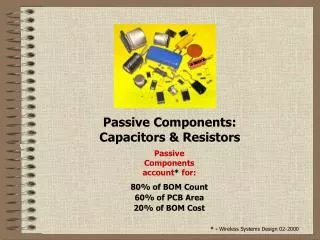
Passive components and circuits - CCP. Lecture 8. Content. Passive el ectronic components – rol e Passive el ectronic components – re s istor s E lectric al properties Clasific ation Paramet ers Mar king Codifica tion. Passive electronic c omponent s - rol e.

E N D
Content • Passive electronic components – role • Passive electronic components – resistors • Electrical properties • Clasification • Parameters • Marking • Codification
Resistor – historyand tendencies • 1827 first resistor • 1976 first integrated resistors • General tendenciesof evolution: • Performances increases • Dimensions decreases • Costs decreases
Resistor – electrical properties • The basic relation for resistance calculusis: Write the values of the resistivities for the main materials used in electronics. http://www.8886.co.uk/ref/resistivity_values.htm http://hyperphysics.phy-astr.gsu.edu/hbase/Tables/rstiv.html#c1 http://www.istonline.org.uk/Handbook/40.pdf
Resistor – equivalent electricscheme • Due to the constructiveparticularities, each resistor has a parasitic inductance and a parasitic capacitance besides the useful resistance. • Parasitic parametersmust be taken into considerationat high frequencies.
For the resistive voltage divider, determine the dividing factor if: R1=1 K; R2=100 R1=100 K; R2=10 K R1=100 K; R2=1 K How is the dividing factor modified with the frequency, if each resistor has a parasitic capacitance equal with 2 pF? Problems
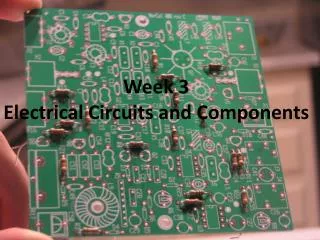
Clasifications – constructiv criterion • Discrete • Fixed • Variable • Integrated • Resistors arrays • Resistor networks • Embedded (includedin the structure) • In the PCB level • In the ceramic sublayer (multicip modules – MCM) • In siliciumwith thin film technology • In theintegrated circuits
Discrete resistors • Fixed • Variable
Integrated resistors • Areas • Networks
Embedded resistors • Decrease of the total cost of manufacturing • Thermodynamic reliability • Decrease of the dimensions • Compatibility between different materials • Values between 10and 200K with tolerancesunder 10%.
Clasification – liniarity criterion • Linear • Non-linear • Thermistors • Varistors • Fotoresistors
Clasification – technological criterion • Pelicular resistors – are obtainedby depositinga resistiv material (aglomerated charbon, christalin charbon,metalic alloys, metalic oxids) into a thin layer (under 10m) on an isolator support. • Reeled (wired) resistors – are obtainedwiringametalic conductor on an isolator support. The technologyis used for obtaining either precision resistorsorhigh-power resistors. • Volume resistors – the resistiv element represents the whole body of the resistor.
Clasification – geometric criterion • It concernes, in general,the way in whichterminalsare connected to thebody of the resistor: • With surface mounted terminals (SMD); • With axial terminals; • With radial terminals;
Parameters of fixed resistors • Parametersthat must be written on the body of the resistor • The nominal resistance • Nominal tolerance value • Parameterswritten only on certain resistors • The nominal dissipated power • The temperature coeficient • The superior limit voltage • Parametersthat are not written (the nominal values’ domain, the nominal domainof temperature, the noise factor)
Series of normalised values • In practice,resistors are not manufacturedwith nominal resistancesin a continuous range of values. • The solutionused is that of a serie of normalisedvalues. Each serie is characterisedby a certain tolerance. • The nominal values of resistancesare obtained from the values of the normalised serie by multiplication with powers of 10. • A certain serie covers almost all the domain of possible valuesfor resistances, taking into account that between two succesiv values of the serie the following relation holds :
Series of normalised values • The number of values in a series results, depending on tolerance, solving the equation on the right and taking the first superior integer for n. • The nominal values of a series are in a geometrical progression given by the following relation:
Series of normalized values • The main normalized seriesare thefollowing: E6(20%); E12(10%); E24(5%); E48(2%); E96(1%); E192(0,5%); • Values of the first three normalized series:
Choosing resistorsdepending on the tolerance • In choosing resistorsfor an applicationan important factor is their tolerance. • The variation of functions of a circuit with respect to the tolerances of the components is called sensitivity.
Nominal power, Pn • Represents the maximum powerthat can be dissipated on a resistor in a regime of prolonged functioningat a temperature equal to the nominal temperature Tn, without it modifying its parameters. • This parameter is written only for resistors with nominal power higher than 2W. • For this parameter there are 24 standardized values: 0,05W; 0,1W; 0,125W; 0,25W; 0,5W; 1W; 2W; 3W; 4W; .... 10W; 16W; ... 500W
Low power resistors • For low power resistors (under 2W) the nominal power can be deducted from the dimensions of the resistor.
Temperature coefficient • Apeareswritten on the body of the resistor only in case of precision resistors. • The parameter is defined as follows: • For most resistors this parameter can be considered constant.
The superior limit voltage, Vn • Apares writtenin the caseof resistors designed for functioning at very high voltages . • For a usual resistor it can be deduced as follows: • For high value resistors, Vn can be limited under the previous value by reasons concerning the dielectrics breakdown.
The noise factor, F • Represents the value of thenoise voltage that appears on the resistor when applying a 1V continuous voltage. • The noise voltage appears due to the disordered movement of the charge carriersin the conductor.
Marking the resistors • Marking refersto the way in which the information written on the resistors is codified. • Markingin the codeof lettersandfigures • Markingin the colors’ code
Markingwiththe codeof lettersandfigures • Marking the nominal value is made using figures and letters as multipiliers. The letter marks the presence of the decimal dot in the nominal value. Multipliers: R=1; K=1.000 (kilo); M=1.000.000 (mega); G=1.000.000.000 (giga) • For tolerance marking one can use either the marking in clear (5%, 1%, etc.) or the letter codified one. B0,1%; C0,25%; D0,5%; F1%; G2%; H2,5%; J5%; K10%; M20%
Markingwiththe codeof lettersandnumbers • To avoid confusions between letters which have the significance of both separator and tolerance, the ones that signify tolerance are written separately from the nominal value code (possibly on another line). Value 2700, tolerance 5% Value 330K, tolerance 20% Value 0,33, tolerance 10% • The marking of the power and the temperature coefficient is made in clear for resistors for which is required to display these parameters.
Markingwiththe codeof lettersandnumbers for SMD resistors • For SMD resistors, with very low dimensions, the following code is used.(cod EIA-96).
Markingwiththe codeofcolors • This type of codified marking, although more difficult to read, has the advantage that the writing is visible on the body of the resistor regardless of its position on the board. • The reading of the code is made starting with the colored ring that is the closest to a terminal or with the group of colored rings. • For resistors with nominal values from the series E6, E12, E24 and E48 the code has only four colored rings. • For resistors with nominal values from the series E96, E192 and with smaller tolerance, the code has five colored rings.
Remarks • Some colors have no significance for tolerance (orange, yellow and white). • In the case of the code with four rings, the only possible colors for tolerance are red (2%), gold (5%) or silver (10%). • The lack of the colored ring for tolerance means the tolerance is 20%. Therefore, in this case the code will have only three colored rings. Brown, black, red +gold =10•100 5%=1K 5%
Codification of resistors • Gives the information by which the resistors are described in catalogs and therefore, also, in the lists of materials that are made. For resistors produced in Romania, the code has the following structure: • Field I – containsthree lettersindicating the technological type; • Field II – contains afigurewith significance concerning the type of capsule (the way the terminals are connected to the body); • Field III – containsthreefigures indicating the nominal power; • Field IV – containsalettersignifying the constructive variant; • In the material liststhese codes are completed with the information written on the resistor(nominal value and tolerance).
Codification of resistors – examples General usage resistor with carbon film (coat) (RCG), with axial terminals (1), nominal power of 1W (100), reliable variant (L), 5,1K, tolerance 5% (J). Resistor with metallic film (coat) (RPM), with radial terminals (3), nominal power 0,5W (050), reliable variant (L), 1K, tolerance 1%.
Codification of resistors • In general, in the electric schemes, next to the symbol of a resistor appears only its reference (R1, R205, etc.) andits nominal value (1K, 3K3, etc.). The power and the tolerance are mentioned only for components that have values different from the others. • This information regarding the codification appears on the equipment schemes as well (assembling plans).
Problems • For a 100 resistor, the tolerance is t=±0,1% at a reference temperatureT0=20 oC. The resistor has a temperature coefficient T=±20ppm/oC. The environmental temperature is between [-30 oC; +90 oC]. • Considering that, due to the dissipated power, the resistor body is heated with 50 oC, whichis the global tolerance of the resistor?
Problems • The resistor body temperature is modified based on the following relation: where TAis environment temperature, and P is the dissipated power.On the resistor is applied a voltage with the waveform presented in the figure bellow. How can be the maximum amplitude of the pulses in order to have the global tolerance lower than tG=±0,3%?
Problems • How is the maximum temperature of environment if the voltage applied on the resistor is sinusoidal with 7V amplitude, and the global tolerance is lower than tG=±0,3%?