EE212 Passive AC Circuits
EE212 Passive AC Circuits. Lecture Notes 3 Transformers. Magnetic Circuit. What is the relationship between magnetic flux and magnetomotive force, F m ? What is the relationship between electric current, i , and magnetomotive force? Magnetic field strength, H = F m / l.

EE212 Passive AC Circuits
E N D
Presentation Transcript
EE212 Passive AC Circuits Lecture Notes 3 Transformers EE 212 2010-2011
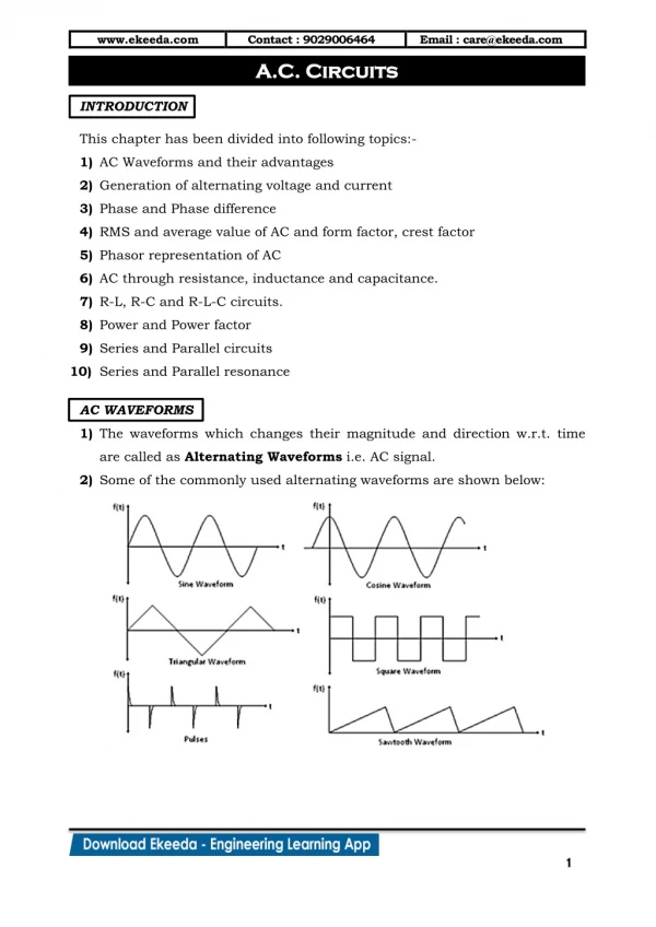
Magnetic Circuit • What is the relationship between magnetic flux and magnetomotive force, Fm? • What is the relationship between electric current, i, and magnetomotive force? Magnetic field strength, H = Fm / l EE 212 2010-2011
Magnetic Circuit • What is Faraday’s Law? • The voltage induced in an electric circuit is proportional to the rate of change of the magnetic flux linking the circuit EE 212 2010-2011
Rm = in ampere-turns/Wb i a di L vab = L dt b Magnetic Circuit Consider a coil around a magnetic core. If a current i flows through the coil, a magnetic flux is generated in the core. = N iin webers (Wb) N = number of turns in the coil Rm = constant known as reluctance (depends on the magnetic path of the flux) Direction of flux by Right-Hand Rule l = length of magnetic path A = cross-section area m = permeability Fingers curled around coil – direction of current Thumb – direction of flux EE 212 2010-2011
Flux Density, B = in teslas, T Magnetic field strength, H = in AT/m B-H Curve B = m H EE 212 2010-2011
f1 i1 a vab L1 b f2 c vcd L2 i2 d Coupled Circuits Circuits that affect each other by mutual magnetic fields ± depending on whether the fluxes add or oppose each other L1, L2: self inductance • M: mutual inductance • ratio of induced voltage in one circuit • to the rate of change of current • in another circuit The flux f2 generated by current i2 in Coil 2 induces a voltage in Coil 1, and vice-versa. EE 212 2010-2011
I1 I2 M a c L1 Vab Vcd L2 b d Coupled Circuits in Phasors If input signals are sinusoidal waveforms, coupled circuits can be in phasor representation • ± depending on flux directions EE 212 2010-2011
Equivalent Circuit with Dependent Sources EE 212 2010-2011
A current i entering a dotted terminal in one coil induces a voltage M with a positive polarity at the dotted terminal of the other coil. f1 i1 a L1 b f2 c L2 I1 i2 a c d L1 L2 d b I2 Dot Convention Dots are placed at one end of each coil, so that currents entering the dots produce fluxes that add each other. The dots provide information on how the coils are wound with respect to each other. (currents entering the dots produce upward fluxes) (+) if both currents enter the dotted terminals (or the undotted terminals). • (-) if one current enters a dotted terminal and the • other current enters an undotted terminal. • Vab = (jwL1) I1 + (jwM) I2 for the currents as shown EE 212 2010-2011
Coefficient of Coupling, k • k = 0 ≤ k ≤ 1 • k depends on the magnetic properties of the flux path. • When k = 0, no coupling • k = 0.01 to 0.1, loosely coupled • k > 0.5, close coupled, e.g. air core • k ≈ 1.0, e.g. power transformer • all the flux generated by one coil is linked to • the other coil (i.e. no leakage flux) • k = 1.0 ideal transformer EE 212 2010-2011
f if + + e1 N1 N2 e2 v1 - - secondary winding primary winding e2 = N2 If + + E2 E1 V1 - - N1 N2 V1 = -E1 If f E1 E2 Transformer When a voltage V1 is applied to the primary winding, an emf e2 is induced in the secondary winding. The induced emf lags the inducing flux by 900. Faraday’s Law EE 212 2010-2011
Transformer Application in Power System • V/I step up/down • Y/D conversion • circuit (dc) isolation • Z matching • (for max power transfer, • min. reflection from load) Instrument Transformers: CT (current transformer) PT or VT (voltage transformer) EE 212 2010-2011
= = a (turns ratio) = = a = Ideal Transformer • No leakage flux Coupling Coefficient, k = 1, i.e. thesame flux f goes through both windings e1 = N1 and e2 = N2 => Turns ratio (a or n) is also known as the transformation ratio. No Losses No voltage drops in the windings: V1 = - e1 Instantaneous powers in primary and secondary are equal (i.e. all the energy from the primary is transferred to the secondary winding). e1 i1 = e2 i2 Therefore, EE 212 2010-2011
I1 I2 + V2 ZL e2 e1 V1 - N1 N2 Transformer Loading • a secondary current I2 is drawn by the load • I2 generates a flux that opposes the mutual flux f (Lenz’s Law: effect opposes the cause) • reduction in f would reduce induced emf e1 • since source voltage V1 is constant, and V1 = - e1, f must remain constant • the primary winding must draw an additional current I’1 from the source to neutralize the demagnetizing effect from the secondary Primary current I1 = I’1 + If EE 212 2010-2011
I1 I2 M a c L1 Vab Vcd L2 b d Ideal Transformer • No leakage flux, i.e., k = 1 • Self-inductance, L1 = L2 = ∞ i.e., magnetizing current = 0 • Coil losses are negligible • With polarities, dots and currents as shown: V2 = V1/a I2 = a I1 Z1= a2Z2 where Z2 is the load impedance + + ● ● - - EE 212 2010-2011
f i1 R1 R2 + + e1 v1 ZL e2 v2 - - N2 N1 Actual Transformer • - resistance in primary and secondary windings • - leakage reactance in pr. and sec. windings • - voltage drops in both windings (leakage impedance) • - losses • - copper loss primary: I12·R1 secondary: I22·R2 • - iron loss (core loss) • Core loss depends on voltage and frequency • eddy current loss hysteresis loss EE 212 2010-2011
Iron (Core) Losses Eddy Current Loss: emf induced in core generates eddy currents which circulate in the core material, generating heat. laminations (silica sheets between core layers) – to reduce eddy current, and minimize loss EE 212 2010-2011
Iron (Core) Losses Hysteresis Loss: The direction of the magnetic flux in the core changes every cycle. Power is consumed to move around the magnetic dipoles in the core material, and energy is dissipated as heat. Hyst. loss (vol. of core) x (area of hyst. loop) EE 212 2010-2011
Transformer Construction • Coil Winding • Core Assembly • Core-Coil Assembly • Tank-up • Accessories Mounting and Finishing EE 212 2010-2011
Core Assembly EE 212 2010-2011
Core-Coil Assembly • Core vertical sides – limbs, top horizontal side – yoke • Yoke is removed to insert the coils into the limbs • LV coil is first placed on the insulated core limbs • Insulating blocks are placed at the top and bottom of the LV coil • Cylinder made out of corrugated paper is placed over the LV Coil • HV coil is placed over the cylinder • The top yoke is fixed in position • LV and HV windings are connected as required EE 212 2010-2011
Tank-up EE 212 2010-2011
Accessories Mounting • Connections of LV and HV coil ends to the terminal bushings are made • Transformer tap changer and protection accessories (e.g. Buchholz relay, Conservator, Breather, temperature indicator, etc.) are installed • Tank is closed Functions of Transformer Oil • Cooling • muffle noise • displace moisture (avoid insulation degradation) EE 212 2010-2011
Transformer Cooling EE 212 2010-2011
Typical Power Transformers Pole-mounted Single-phase Transformer Three-phase Transformer EE 212 2010-2011
Transformer Rating • Rated kVA • Rated Voltage primary and secondary: (transformers are normally operated close to their rated voltages) • Rated Current (FL Current) is the maximum continuous current the transformer can withstand For single phase transformer: Rated primary current = Rated VA / Rated Pr Voltage When rated current flows through a transformer, it said to be fully loaded. The actual current through a transformer varies depending on the load connected at different times of the day. EE 212 2010-2011
Equivalent Circuit Represent inductively coupled circuits by a conductively connected circuit Equivalence in terms of loop equations Assume a load impedance is connected to the secondary. turns ratio, = a R2 R1 M + + V2 V1 L11 L22 I2 I1 - - N1 N2 KVL at Loop 1: -V1 + R1I1 + jwL11I1 - jwM I2 = 0 KVL at Loop 2: R2I2 + V2+ jwL22I2 - jwM I1 = 0 inductively coupled circuits The loop equations are: EE 212 2010-2011
Equivalent Circuit (continued) L1 R1 V1 - V2 I1 I2 a2L2 a2R2 + + aM V1 I1 aV2 - - R1 + jwL11- jwM - jwMR2 + jwL22 = Consider following substitutions: M a·ML2a2·L2R2a2·R2 V2a·V2I2 conductively connected circuit KVL at Loop 1: -V1 + R1I1 + jwL1I1 + jwaM (I1-I2/a) = 0 KVL at Loop 2: jwaM (I2/a - I1) + jw a2L2.I2/a + jw a2R2.I2/a + aV1 = 0 Let L11= L1 + aM and L22= L2 + M/a The loop equations remain the same: EE 212 2010-2011
Transformer Equivalent Circuit a2X2 X1 a2R2 R1 + I1 Ie If a2ZL Ic V1 Xf Rc - ZL = load impedance Ie = excitation current If = magnetizing current Xf = magnetizing reactance equivalent circuit referred to the primary side R1, R2= primary, secondary winding resistance X1, X2= primary, secondary leakage reactance I1, I2= primary, secondary current Rc = core loss resistance (equivalent resistance contributing to core loss) Ic = core loss equivalent current EE 212 2010-2011
Example: Transformer Equivalent Circuit a) b) j0.92/a2 W j0.0090 W 0.72/a2 W 0.0070W j44.6429 W 308.642 W j0.92W j0.0090a2W 0.72W 0.0070a2 W j44.6429 a2W 308.642a2 W A 50-kVA, 2400/240-V, 60-Hzdistribution transformer has a leakage impedance of (0.72 + j0.92) Win the high voltage (HV) side and (0.0070 + j0.0090) W in the low voltage (LV) winding. At rated voltage and frequency, the admittance of the shunt branch of the equivalent circuit is (0.324 – j2.24)x10-2S [siemens]when viewed from the LV side. Draw the circuit: a) viewed from the LV side b) viewed from the HV side Turns ratio, a = 2400/240 = 10 EE 212 2010-2011
Transformer: Approximate Equivalent Circuit Xe Re Xf Rc Xe Re Xe Re = R1 + a2R2 Xe = X1 + a2X2 where, R2 and X2 are referred to the primary side Re and Xe obtained from Short Circuit Test Rc and Xf obtained from Open Circuit Test For transformers operating close to full load For transformers in a large power network analysis EE 212 2010-2011
Short Circuit Test P = copper loss = I2 Re Re = Ze = Xe = + R1 ≈ a2 R2 ≈ Vsupply X1 ≈ a2 X2 ≈ - HV LV W V A Xe Re I + V Xf Rc - • Connect meters on HV side as shown • Short circuit LV side • Energize HV side with a variable voltage source and increase voltage gradually to get rated current reading on the Ammeter • Take the V, I and P readings from meters Equivalent circuit referred to HV side EE 212 2010-2011
Open Circuit Test P = core loss = Rc = + Ie = I , Ic = Vsupply If = Xf = - HV LV W V A I + Ie If V Ic Rc Xf - • Connect meters on LV side as shown • Open circuit HV side • Energize LV side with rated voltage • Take the V, I and P readings from meters Equivalent circuit referred to LV side EE 212 2010-2011
Transformer Efficiency Efficiency, h = Power Output / Power Input Power Output = |VL| |IL| cos = |IL|2 RL Power Input = Power Output + Cu losses + Core losses Cu Loss – varies with load current Core Loss – depends on voltage (usually a constant for practical purposes) Transformer efficiency is maximum when Cu loss = core loss EE 212 2010-2011
Transformer Efficiency (continued) • Power transformers: - usually operate at rated capacity, • - designed to have max. h at full load • Distribution transformers: carry a widely varying load -designed to have max. h at less than full load • - always energized despite load levels – designed to have low core loss EE 212 2010-2011
Example: Transformer Find the equivalent circuit of a 50-kVA, 2400/240-V transformer. The following readings were obtained from short circuit and open circuit tests: • If rated voltage is available at the load terminals, calculate the transformer efficiency at • full load with 0.8 p.f. lagging • (b) 60% load with 0.8 p.f. lagging. • What is the voltage at the HV terminals of the transformer? • If rated voltage is applied at the primary terminals, calculate the transformer efficiency at • full load with 0.8 p.f. lagging EE 212 2010-2011
Transformer Example 2 • The transformer is used to step down the voltage at the load end of a feeder whose impedance is 0.3 + j1.6 ohm. The voltage at the sending end of the feeder is 2400 V. Find the voltage at the load terminals when the connected load is • Zero • 60% load at 0.8 p.f. lagging • Full load at 0.8 p.f. laging • Full load at 0.5 p.f. leading • What will be the current on the low voltage side if a short circuit occurs at the load point? EE 212 2010-2011
Voltage Regulation • When a constant rated voltage is applied to the primary, • At no load - no current, and therefore no voltage drop in transformer - secondary voltage, Vsec = rated voltage • As load (resistive or inductive) increases - voltage drop in transformer (Vdrop) increases • - secondary voltage decreases (reverse is the case with capacitive load increase) EE 212 2010-2011
Voltage Regulation (continued) To maintain rated voltage at the secondary, At no load, primary voltage required, Vpr = rated voltage At a certain load, required Vpr = rated voltage + Vdrop in transformer Voltage regulation is the change in primary voltage required to keep the secondary voltage constant from no load to full load, expressed as a percentage of rated primary voltage. Load p.f. has a big effect on voltage regulation. EE 212 2010-2011
Example • A 50-kVA, 2400/240-V, 60-Hz transformer has a leakage impedance of (1.42+j1.82) ohms on the HV side. The transformer is operating at full load in all 3 cases below. • 1. Calculate the voltage regulation at • 0.8 p.f. lagging • unity p.f. • 0.5 p.f. leading EE 212 2010-2011
Voltage Control The allowable voltage variation at the customer load point is usually ± 5% of the rated (nominal) value. Control measures are taken to maintain the voltage within the limits. • Use of transformer tap changers: on-load/off-load • Injecting reactive power (Vars): series/shunt compensation EE 212 2010-2011
Autotransformers • Used where electrical isolation between primary side and secondary side is not required. • Usually relatively low power transformers • Can be readily made to be variable. • Can think of it as two separate windings connected in series. • Usually it is a single winding with a tap point. • Can be used as either step-up or step-down transformer EE 212 2010-2011
Autotransformers (continued) • Schematic diagrams: From J.D. Irwin, “Basic Engineering Circuit Analysis”, 3rd ed. Macmillan EE 212 2010-2011
Autotransformers (continued) From Jackson et al. “Introduction to Electric Circuits” 8th ed., Oxford EE 212 2010-2011
Autotransformers (continued) Assume N1 = 200 and N2 = 100 Let Vsource = 120 V Then what is V2? Assume I2 is 15 A. Then Sload = ?, and Ssource = ? EE 212 2010-2011
Autotransformers (continued) What is the node equation at the tap? Node equation: I1 + IZY = I2 therefore, IZY = From transformer action: N1I1 = N2IZY therefore, That is, only part of the load current is due to the magnetomotive force that the current in the primary coil exerts on the secondary coil. The remaining portion is direct conduction of the source current to the load. EE 212 2010-2011