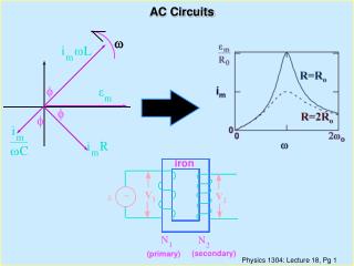
AC CIRCUITS 90523
AC CIRCUITS 90523. NCEA Level 3 Physics. AC CIRCUITS. RMS Values - Mains electricity - Power - Root mean square AC in capacitance - Intro - Reactance - Phase relationship for capacitance AC in inductance - Intro - Reactance - Phase relationship for reactance

AC CIRCUITS 90523
E N D
Presentation Transcript
AC CIRCUITS90523 NCEA Level 3 Physics
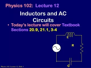
AC CIRCUITS • RMS Values - Mains electricity - Power - Root mean square • AC in capacitance - Intro - Reactance - Phase relationship for capacitance • AC in inductance - Intro - Reactance - Phase relationship for reactance • Addition of alternating voltages - AC in an RC circuit - AC in an RL circuit • Resonance • Exercise 9 (AC Circuits): Page 150 - 151 Page 152 - 153 Page 154 - 155 Page 156 - 160 Page 161 - 165 Page 166 - 173
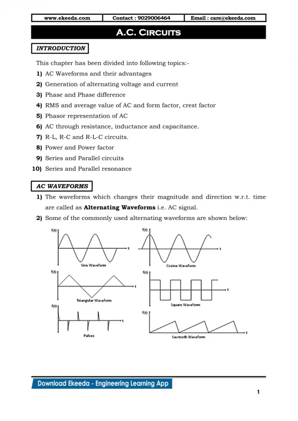
RMS VALUES All mains electricity in New Zealand is made in hydro-electric dams. These are huge alternators that turn giant magnets within a nest of metal coils. The result of this is that the poles of the alternators alternate at 50 times per second, 50Hz. This produces Alternating Current or AC. The equation for changing voltage is: Voltage changes as a coil rotates + V = V max sin t 3T/4 V t T/4 - ‘I’ In T T/2 ‘I’ Out N S Coil rotations at different stages of the time period, T.
When this voltage is applied to a resistive circuit, the resulting current will also be alternating and sinusoidal: I = V/R I = (Vmax sint) /R Thus: I = Imax sint Remember that in rotational motion, which a coil is doing, that = t V = Vmax sin and I = Imax sin AC is widely used in industry and homes as the power supply for electrical appliances because: Produced by generators The maximum voltage can b changed easily with a transformer. It can be controlled by a wide range of components; R; C & L’s. The frequency of AC is essential for timing
Most mains electricity is used for heating effect. The power dissipated in a resistance is given by P = VI. We can also write this as P = I2R substituting in V= IR into the above equation. As current varies with time so must power. Voltage and current in an AC circuit produces a cyclic power output. Peak power output Power (Watt) Average power output t (s) One cycle (T) WHY ARE ALL THE PEAKS POSITIVE? ANS: when power is calculated by P = IV when I and V are both negative when mutiplied together they always produce a positive
Example 1: WORK THROUGH THE EXERCISE ON POWER FROM THE WORKSHEET
RMS: This stands for root mean square. This is a way of “averaging out” the effect of the AC as the voltage and current are always changing. The RMS is the DC value which produces the same power output. The RMS values of voltage and current may be used directly in power formulae as stated earlier. P = VRMS IRMS P = I2RMSR For sinusoidal alternating current, it can be shown that: IRMS = IMAX VRMS = VMAX & 2 2 RMS values are so useful that any values quoted or measured will be the RMS values rather than the maximum values.
Example 2: • The household power supply in NZ is 240V AC at 50Hz. • Find the peak voltage of the household supply • Sketch a graph of voltage against time for one cycle, with appropriate values on the axis. • Find the peak and RMS value of the current in a 100W lamp connected to the household supply. • SOLUTION: • 240V refers to the rms voltage. • The peak voltage Vmax = Vrms x 2 • = 240 x 2 • = 340V • Frequency f = 50Hz • T = 1/f = 1/50 • = 0.20s
Vmax 340V 240V Vrms t(s) V 0.01 0.02 -240V -340V c. The ‘wattage’ of the lamp refers to its power output. P = Vrms x Irms [rms values must be used in the power formula] Irms = P / Vrms = 100 / 240 = 0.42A IPEAK = Irms x 2 = 0.42 x 2 = 0.59A
READ THROUGH “RMS VALUES” PAGE 150 - 151 & COMPLETE QUESTIONS 1 – 2 S & C
AC IN CAPACITANCE: In a DC circuit containing a capacitor the current will only flow until the capacitor is full. In an AC circuit the flow alternates thus the capacitor charges and discharges 50 times a second. The lamp continually glows. C C Lamp will not glow when capacitor is fully charged Lamp will continue to glow as capacitor is continually charging and discharging
REACTANCE: Readings of the capacitor voltage, VC, can be made for different values of current, I. This shows that the VC is proportional to the current, I. VC(V) VC I There must therefore be a constant joining the two variables. The constant is called the reactance, XC. AC current, I (A) XC = gradient VC= IXC OR XC= VC/I Reactance is basically the resistance that the capacitor actually has to the AC current.
FACTORS AFFECTING THE REACTANCE OF THE CAPACITOR: • Reactance depends upon: • The capacitance, C, of the capacitor. • The frequency, f, of the AC supply. • The following observations have been made: The larger the capacitance the smaller the reactance as larger capacitors store more charge. Reactance is inversely proportional to the capacitance. The greater the frequency, the smaller the reactance. When the frequency, f, high, charge is flowing on and off the capacitor plates at a high rate. XC 1/C XC 1/f XC 1/Cf
The proportionality constant in this relationship is: 1/2 The reactance of a capacitor C, with supply of frequency F, is given by: XC = 1/2fC OR XC = 1/C (Since 2f = )
Example 3: • A 100F capacitor is connected to a 12Vrms 50Hz AC supply. • Calculate: • The reactance of the capacitor at the frequency. • The rms current in the circuit. • SOLUTION: • XC = 1/2fC • = 1 / (2 x 50 x 100x10-6) • = 32Ω • Irms = Vrms / XC • = 12 / 31.8310 • = 0.38A
PHASE RELATIONSHIP FOR CAPACITANCE: VS In a DC circuit the voltages across the components connected in series with a supply add up to the supply voltage. VS = VC + VR In AC containing ‘C’ and ‘R’ this does not apply. Why? ANS: the two voltages are out of phase C R VC VR +Vnax t (s) 0 Vnax T/4 T/2 3T/4 T -Vnax VOLTAGE vs TIME GRAPH PHASOR DIAGRAM
VR Phasor diagram for t = 0 on resistor voltage-time graph VR t VC Phasor diagram for t = 0 on capacitor voltage-time graph t VC The angle between the phasors is 90o. The phasor VR is ahead of the phasor VC. These phasors are vectors and thus must be treated as so. The supply voltage, VS, is thus the two phasor vectors added together. VR VR VS VC VS VC
Example 4: • In the circuit opposite, VR was measured as 6.0V and VC was measured as 8.0V. • Calculate the supply voltage. • Calculate the phase difference between the supply voltage and the resistor voltage. VS SOLUTION: a. VS = 6.0 + 8.0 = 6.02 + 8.02 = 10V b. = tan-1 (8.0/6.0) = 53o C 6.0V R VS VC VR 8.0V C = 100F R = 25Ω
Example 5: • A 5.0Ω and 500F capacitor are connected in series with a 50Hz AC supply. The voltage across the resistor is measured as 2.0V (rms) and across the capacitor as 2.5V (rms). • Find: • The rms current in the circuit. • The supply voltage, VS. • The phase difference between the supply voltage and the current. VS 50Hz C = 500F R=5.0Ω VC 2V
SOLUTION: a. Current, I, is calculated from the voltage across the resistor, VR. I = V/R = 2.0/5.0 = 0.40A b. VS2 = VC2 + VR2 = (2.52 + 2.02) = 3.2V c. As the resistor voltage is in phase with the current, is the phase difference. = tan-1 (2.5/2.0) = 51O VR = 2.0V VC = 2.5V VS
IMPEDANCE: Resistance and reactance both impede the flow of current in a circuit. The combined effect of resistance and reactance is called impedance, symbol Z, unit Ohm (Ω). Just as VR = IR for resistor And VC = IXC for a capacitor, VS = IZ for the whole circuit. R Z = R2 + XC2 Thus: Z XC
Example 6: • In an experiment a 10V, 50Hz AC supply was connected in turn to: • A resistor • A capacitor • Both the resistor and capacitor together in series. • In each case the current was measured, with the results as shown 10V 50Hz 10V 50Hz 10V 50Hz C 0.50A 0.25A C A A A R R • Find: • The resistance of R. • The reactance of capacitor, C. • The capacitance of C. d. The impedance of the circuit containing both R & C. e. The current in the circuit containing both R & C.
SOLUTION: • R = VR / I • = 10/0.50 • = 20Ω • XC = VC / I • = 10/0.25 • = 40Ω • c. XC = 1/2fC • = 1 / (2 x 50 x 40) • = 80x10-6 F • Z = R2 + XC2 • = 202 + 402 • = 45Ω e. I = VS /Z = 10 / 44.7 = 0.22A
READ THROUGH “AC IN CAPACITANCE PAGE 152-153 & COMPLETE QUESTIONS 3 S & C
AC IN INDUCTANCE: Inductors always oppose a change in current, so in an AC circuit where the current is continually changing, the inductor will act to limit the amount of current. A voltage is induced across the inductor whenever the current (and hence the flux) in it is changing. When ‘L’ is linked to AC the current is always changing thus there is a continual voltage, VL across the inductor. The voltage will act against the current according to Lenz’s law. Using the rheostat the relationship between current and inductor voltage can be investigated R A L VL
REACTANCE: Readings of the inductor voltage, VL, can be made for different values of current, I. This shows that the VL is proportional to the current, I. VL(V) VL I There must therefore be a constant joining the two variables. The constant is called the reactance, XL. AC current, I (A) XL = gradient VL= IXL OR XL= VL/I Reactance is basically the resistance that the inductor actually has to the AC current. Real inductors do have resistance but at this level, unless otherwise stated, the resistance is said to be negligible.
FACTORS AFFECTING THE REACTANCE OF THE INDUCTOR: • Reactance depends upon: • The inductance, L, of the inductor. • The frequency, f, of the AC supply. • The following observations have been made: The larger the inductance the larger the reactance this is due to greater inductance causing a greater opposing voltage and therefore a smaller current. Reactance is proportional to the inductance. The greater the frequency, the smaller the current. When the frequency, f, high, the opposing voltage will be greater causing a smaller current. Reactance is proportional to the frequency. XL L XL f XL Lf
The proportionality constant in this relationship is: 2 The reactance of a inductor L, with supply of frequency f, is given by: XL= 2fL OR XL = L (Since 2f = )
Example 7: A 0.50H inductor is connected to a 10V 50Hz AC supply. Assuming the inductor has negligible resistance, what is: a. The reactance of the inductance? b. The current in the circuit? • SOLUTION: • XL = 2fL • = 2 x 50 x 0.50 • = 160Ω • I = VL / XL • = 10 / 157 • = 0.064A
PHASE RELATIONSHIP FOR INDUCTANCE: VS In a DC circuit the voltages across the components connected in series with a supply add up to the supply voltage. VS = VL + VR In AC containing ‘L’ and ‘R’ this does not apply. Why? ANS: the two voltages are out of phase L R VL VR +Vnax t (s) 0 Vnax T/4 T/2 3T/4 T -Vnax VOLTAGE vs TIME GRAPH PHASOR DIAGRAM
VR Phasor diagram for t = 0 on resistor voltage-time graph VR t VL Phasor diagram for t = 0 on inductor voltage-time graph VL t The angle between the phasors is 90o. The phasor VR is behind of the phasor VL. These phasors are vectors and thus must be treated as so. The supply voltage, VS, is thus the two phasor vectors added together. VL VS VR VS VR VL
Example 8: • A 940Ω resistor and a 2.0H inductor are connected to 100Hz AC supply. The current in the circuit is 3.2mA (rms). • Find: • The resistor voltage VR. • The inductor voltage VL. • The supply voltage VS. • The phase difference between the supply voltage and current. SOLUTION: a. VR = I x R = 0.0032 x 940 = 3.0V b. VL = I x 2fL = 0.0032 x 2 x 100 x 2.0 = 4.0V
c. VS2= VL2 + VR2 = 42 + 32 = 25 = 5.0V d. The current is in phase with the resistor voltage, and so is the phase difference: = tan-1 (4.0/3.0) = 53O The supply voltage leads the current by 53O. VS VL = 4.0V VR = 3.0V
IMPEDANCE: Resistance and reactance both impede the flow of current in a circuit. The combined effect of resistance and reactance is called impedance, symbol Z, unit Ohm (Ω). Just as VR = IR for resistor And VL = IXL for a inductor, VS = IZ for the whole circuit. Z = R2 + XL2 Thus: XL Z R
Example 9: A real 380mH inductor can be regarded as a pure inductance in series with its resistance, R. 10V DC 10V AC 50Hz A 0.20A A 0.20A L=380H L=380H R R When connected to a 10V DC supply, a current of 0.20A flows. It is connected to a 10V 50Hz AC supply. • Find: • The resistance of R. • The reactance of the inductor. • The impedance in the AC circuit. d. The current when connected to the AC supply.
SOLUTION: • R = VDC / IDC • = 10/0.20 • = 50Ω • XL = 2fL • = 2 x 50 x 380x10-3 • = 120Ω • c. Z = R2 + XL2 • = 502 + 119.3812 • = 130Ω • I = VS / Z • = 10 / 129.428 • = 0.077A
READ THROUGH “AC IN INDUCTANCE” PAGE 154 - 155 & COMPLETE QUESTIONS 4 S & C
READ THROUGH “ADDITION OF ALTERNATING VOLTAGES” PAGE 156 - 160 & COMPLETE QUESTIONS 5 - 7 S & C
RESONANCE: LCR SERIES CIRCUIT: When a capacitor, inductor and resistor are connected in series to an AC supply they form a very useful circuit with some important properties. The voltages and impedance in an LCR circuit will vary considerably as the frequency is changed. The voltage across any of the components in the circuit will depend on the reactance/resistance of the component. VR = IR R is constant & in phase with I VC = IXC XC = 1 /2fC, 90o behind I VL = IXL XL = 2fL, 90o ahead I Although the resistance remains constant in the circuit the reactance’s depend upon the frequency. In order to show how the reactance s vary is to consider a phasor type diagram for the impedance of the circuit.
VARIABLE FREQUENCY AC XL = 2fL R Constant voltage A R Phasor diagram of resistance and reactance’s XC = 1/2fC L C An LCR circuit In the above phasor diagram the total reactance is the difference between the inductor reactance and the capacitor reactance. XT = XC - XL If the frequency of the supply is increased, the inductor reactance will increase but the capacitor reactance will decrease, as inversely proportional to the f.
In order to find the impedance of the circuit the total reactance is combined with the resistance: R XL - XC R XL - XC Z Z = R2 + (XL - XC)2 In order to find the supply voltage of the circuit the VC and VL is combined with VR: VR VR VL - VC VL - VC VS VS = VR2 + (VL - VC)2
Example 10: • For the circuit shown, the frequency of the supply was set to 50Hz. • Calculate: • The total reactance in the circuit. • The impedance of the circuit. • The phase difference between the supply voltage and the current. VARIABLE FREQUENCY AC Constant voltage A R L=40mH 130 turns C=100F 12Ω
SOLUTION: • XC = 1/2fC • = 1/2 x 50 x 100x10-6 • = 32Ω • XL = 2fL • = 13Ω • XT = XC – XL • = 32 – 13 • = 19Ω • b. Z = R2 + XT2 • = 122 + 19.264622 • = 23Ω c. Because the impedance diagram is mathematically similar to the voltage phasor diagram, the angle is the angle between the current and the resistor voltage. = tan-1 (19.264/12) = 58O The current leads the supply voltage by 58O. I R XC - XL Z
RESONANCE Resonance is a phenomenon that deals with changing frequency. We have already seen that reactance is effected by a change in frequency. XL is proportional to frequency XC is inversely proportional to frequency. If we were to analysis the affect of changing the frequency on the change in current we get a graph shown below: I (A) fo = resonant frequency f (Hz) fo The observations show that the current reaches a maximum at a specific frequency called the resonant frequency. After this as the frequency increases the current decreases.
When the resonant frequency has been reached we stated that the circuit has been tuned. We know that current is inversely proportional to impedance as: I = VS/Z When I = max then Z = minimum. We know that Z is dependent on R (which doesn’t change) & reactance, X (which changes with frequency). From what we have learnt already: At high frequencies: XL > XC XL < XC At low frequencies: XL = XC fohas been reached when: At this point XL- XC = 0 & so: Z = R As Z is minimum this is therefore fo.
Resonance occurs when: XL = XC As: XL= 2fL & XC = 1/2fC Then: 2foL = 1/2foC Thus: fo = 1/[2(LC)]
Example 11: A 120Ω resistor, a 2.00H inductor and a 4.50F capacitor are connected in series to a 15V variable frequency AC supply. Calculate the resonant frequency: VARIABLE FREQUENCY AC VAC = 15V R SOLUTION: At resonance: XL = XC fo = 1/2LC fo = 1/[2(2.00 x 4.50x10-6)] = 53.1Hz C=4.50F 120Ω L = 2.00H
WHAT HAPPENS TO THE VOLTAGE AT RESONANCE? We know that at resonance XL = XC. Thus: VL/I > VC/I As [VC = IXC & VL = IXL] As I is a constant throughout a series circuit it can be cancelled out leaving: VL = VC Z = R At resonance we have found that: VL = VC & Vs = VR As: VL VS = VR Thus: VS = IZ or IR VR = IR VC
Example 12: • An LCR circuit is tuned to resonance and the current is measured as 20mA. The inductor (which is assumed to have negligible resistance) has a voltage of 20V across it. • Find: • The capacitor voltage, VC. • The resistor voltage, VR. • The supply voltage, VS. VS A 0.020A 900Ω VR 20V VC
SOLUTION: a. At resonance, VC = VL so VC = 20V b. VR = I x R = 0.020 x 900 = 18V c. At resonance, since VC = VL, the supply voltage is the same as VR. VS = 18V