Power in AC Circuits
Chapter 16. Power in AC Circuits. Introduction Power in Resistive Components Power in Capacitors Power in Inductors Circuits with Resistance and Reactance Active and Reactive Power Power Factor Correction Power Transfer Three-Phase Systems Power Measurement. 16.1. Introduction.


Power in AC Circuits
E N D
Presentation Transcript
Chapter 16 Power in AC Circuits • Introduction • Power in Resistive Components • Power in Capacitors • Power in Inductors • Circuits with Resistance and Reactance • Active and Reactive Power • Power Factor Correction • Power Transfer • Three-Phase Systems • Power Measurement
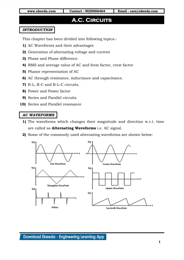
16.1 Introduction • The instantaneous power dissipated in a component is a product of the instantaneous voltage and the instantaneous current p = vi • In a resistive circuit the voltage and current are in phase – calculation of p is straightforward • In reactive circuits, there will normally be some phase shift between v and i, and calculating the power becomes more complicated
16.2 Power in Resistive Components • Suppose a voltage v = Vp sin t is applied across a resistance R. The resultant current i will be • The result power p will be • The average value of (1 - cos 2t) is 1, so where V and I are the r.m.s. voltage and current
16.3 Power in Capacitors • From our discussion of capacitors we know that the current leads the voltage by 90. Therefore, if a voltage v = Vp sin t is applied across a capacitance C, the current will be given by i = Ip cos t • Then • The average power is zero
16.4 Power in Inductors • From our discussion of inductors we know that the current lags the voltage by 90. Therefore, if a voltage v = Vp sin t is applied across an inductance L, the current will be given by i = -Ip cos t • Therefore • Again the average power is zero
16.5 Circuit with Resistance and Reactance • When a sinusoidal voltage v = Vp sin t is applied across a circuit with resistance and reactance, the current will be of the general formi = Ip sin (t - ) • Therefore, the instantaneous power, p is given by
The expression for p has two components • The second part oscillates at 2 and has an average value of zero over a complete cycle • this is the power that is stored in the reactive elements and then returned to the circuit within each cycle • The first part represents the power dissipated in resistive components. Average power dissipation is
The average power dissipation given by is termed the active power in the circuit and is measured in watts (W) • The product of the r.m.s. voltage and current VI is termed the apparent power, S. To avoid confusion this is given the units of volt amperes (VA)
From the above discussion it is clear that • In other words, the active power is the apparent power times the cosine of the phase angle. • This cosine is referred to as the power factor
16.6 Active and Reactive Power • When a circuit has resistive and reactive parts, the resultant power has 2 parts: • The first is dissipated in the resistive element. This is the active power, P • The second is stored and returned by the reactive element. This is the reactive power, Q , which has units of volt amperes reactive or var • While reactive power is not dissipated it does have an effect on the system • for example, it increases the current that must be supplied and increases losses with cables
Consider an RL circuit • the relationshipbetween the variousforms of power canbe illustrated usinga power triangle
Therefore Active Power P = VI cos watts Reactive Power Q = VI sin var Apparent Power S = VI VA S2 = P2 + Q2
16.7 Power Factor Correction • Power factor is particularly important in high-power applications • Inductive loads have a lagging power factor • Capacitive loads have a leading power factor • Many high-power devices are inductive • a typical AC motor has a power factor of 0.9 lagging • the total load on the national grid is 0.8-0.9 lagging • this leads to major efficiencies • power companies therefore penalise industrial users who introduce a poor power factor
The problem of poor power factor is tackled by adding additional components to bring the power factor back closer to unity • a capacitor of an appropriate size in parallel with a lagging load can ‘cancel out’ the inductive element • this is power factor correction • a capacitor can also be used in series but this is less common (since this alters the load voltage) • for examples of power factor correction see Examples 16.2 and 16.3 in the course text
16.8 Power Transfer • When looking at amplifiers, we noted that maximum power transfer occurs in resistive systems when the load resistance is equal to the output resistance • this is an example of matching • When the output of a circuit has a reactive element maximum power transfer is achieved when the load impedance is equal to the complex conjugate of the output impedance • this is the maximum power transfer theorem
Thus if the output impedance Zo = R + jX, maximum power transfer will occur with a load ZL = R - jX
16.9 Three-Phase Systems • So far, our discussion of AC systems has been restricted to single-phase arrangement • as in conventional domestic supplies • In high-power industrial applications we often use three-phase arrangements • these have three supplies, differing in phase by 120 • phases are labeled red, yellow and blue (R, Y & B)
Relationship between the phases in a three-phase arrangement
16.10 Power Measurement • When using AC, power is determined not only by the r.m.s. values of the voltage and current, but also by the phase angle (which determines the power factor) • consequently, you cannot determine the power from independent measurements of current and voltage • In single-phase systems power is normally measured using an electrodynamic wattmeter • measures power directly using a single meter which effectively multiplies instantaneous current and voltage
In three-phase systems we need to sum the power taken from the various phases • in three-wire arrangements we can deduce the total power from measurements using 2 wattmeter • in a four-wire system it may be necessary to use 3 wattmeter • in balanced systems (systems that take equal power from each phase) a single wattmeter can be used, its reading being multiplied by 3 to get the total power
Key Points • In resistive circuits the average power is equal to VI, where V and I are r.m.s. values • In a capacitor the current leads the voltage by 90 and the average power is zero • In an inductor the current lags the voltage by 90 and the average power is zero • In circuits with both resistive and reactive elements, the average power is VI cos • The term cos is called the power factor • Power factor correction is important in high-power systems • High-power systems often use three-phase arrangements