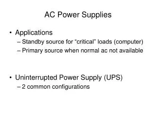
AC Power
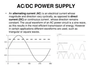
AC Power. AC Power. As in the case with DC power, the instantaneous electric power in an AC circuit is given by P = VI , but these quantities are continuously varying. Almost always the desired power in an AC circuit is the average power , which is given by. P avg = V I cos .

AC Power
E N D
Presentation Transcript
AC Power As in the case with DC power, the instantaneous electric power in an AC circuit is given by P = VI, but these quantities are continuously varying. Almost always the desired power in an AC circuit is the average power, which is given by Pavg = V I cos where is the phase angle between the current and the voltage and V and I are understood to be the effective or rms values of the voltage and current. The term cos is called the "power factor" for the circuit.
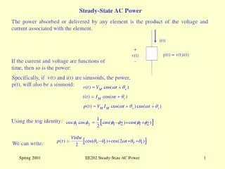
Instantaneous Power As in DC circuits, the instantaneous electric power in an AC circuit is given by P=VI where V and I are the instantaneous voltage and current. Since then the instantaneous power at any time t can be expressed as
the power becomes: Averaging this power over a complete cycle gives the average power. Average Power Normally the average power is the power of interest in AC circuits. Since the expression for the instantaneous power is a continuously varying one with time, the average must be obtained by integration. Averaging over one period T of the sinusoidal function will give the average power. The second term in the power expression above averages to zero since it is an odd function of t. The average of the first term is given by
and the average power can be expressed as
Average Power Integral Finding the value of the average power for sinusoidal voltages involves the integral The period T of the sinusoid is related to the angular frequency and angle by Using these relationships, the integral above can be recast in the form: Which can be shown using the trig identity: which reduces the integral to the value 1/2 since the second term on the right has an integral of zero over the full period.
RLC Series Circuit The RLC series circuit is a very important example of a resonant circuit. It has a minimum of impedance Z=R at the resonant frequency, and the phase angle is equal to zero at resonance.
Single-phase System The Sinusoidal voltage v(t) = Vm sin wt where Vm = the amplitude of the sinusoid w = the angular frequency in radian/s t = time
A more general expression for the sinusoid (as shown in the figure): v(t) = Vm sin (wt + q) whereqis the phase angle Single-phase System
Single-phase System A sinusoid can be expressed in either sine or cosine form. When comparing two sinusoids, it is expedient to express both as either sine or cosine with positive amplitudes. We can transform a sinusoid from sine to cosine form or vice versa using this relationship: sin (ωt ± 180o) = - sin ωt cos (ωt ± 180o) = - cos ωt sin (ωt ± 90o) = ± cos ωt cos (ωt ± 90o) = + sin ωt
Single-phase System Apparent Power, Reactive Power and Power Factor The apparent power is the product of the rms values of voltage and current. The reactive power is a measure of the energy exchange between the source and the load reactive part.
Single-phase System The power factor is the cosine of the phase difference between voltage and current. The complex power:
Generation of Three-phase In a three phase system the source consists of three sinusoidal voltages. For a balanced source, the three sources have equal magnitudes and are phase displaced from one another by 120 electrical degrees. A three-phase system is superior economically and advantage, and for an operating of view, to a single-phase system. In a balanced three phase system the power delivered to the load is constant at all times, whereas in a single-phase system the power pulsates with time.
Generation of Three-phase Suppose three similar loops of wire with terminals R-R’, Y-Y’ and B-B’ are fixed to one another at angles of 120o and rotating in a magnetic field.
Generation of Three-phase The instantaneous e.m.f. generated in phase R, Y and B: vR= VRsin wt vY= VY sin (wt -120o) vB= VB sin (wt -240o)= VBsin (wt +120o)
Phase sequences: • RYB or positive sequence Generation of Three-phase VR leads VY, which in turn leads VB This sequence is produced when the rotor rotates in the counterclockwise direction
Generation of Three-phase (b) RBY or negative sequence VR leads VB, which in turn leads VY This sequence is produced when the rotor rotates in the clockwise direction
Star Connection Three wire system
Wye Connection Line-to-neutral voltages: # Reference: VRN # Positive sequence
Delta Connection Line-to-line currents: # Reference: IRY # Positive sequence.
Vector diagram • Phasor diagram is used to • visualize the system voltages • • Wye system has two type of • voltages: Line-to-neutral, and • line-to-line • • The line-to-neutral voltages are • shifted with 120 degrees • • The line-to-line voltage leads • the line to neutral voltage with • 30 degrees • • The line-to-line voltage is times • the line-to-neutral voltage
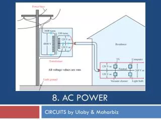
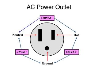
TNB SUPPLY SYSTEM Voltage 3 phase, 50 Hz The main transmission and substation network are: - 275 kV - 132 kV - 66 kV The distribution are: - 33 kV - 22 kV - 11 kV - 6.6 kV - 415 volts - 240 volts (single phase) drawn from 415 volts 3 phase (phase voltage), between line (R, Y, B) and Neutral (N)
SYSTEM The low voltage system (415/240 V) is 3-phase four wire. The low voltage system is a mixture of overhead lines and under ground cables. The high voltage and extra high voltage system is 3-phase three wire Configuration. Overhead line and under ground cable system are used. Supply Method (two types of premises) 1. Single consumer such as private dwelling house, workshop, factory, etc • Single phase, two wire, 240 V, up to 12 kVA max demand • Three phase, four wire, 415 V, up to 45 kVA max demand • Three phase, four wire, C. T. metered 415 V, up to 1,500 kVA max • demand
2. Multi tenanted premises, such as high rises flats, commercial, office blocks, etc • Low Voltage Three phase, four wire, C.T. metered 415 V, up to 1,500 kVA max demand • High Voltage and Extra High Voltage • Three phase, three wires, 6,600 and 11,000 V for load of 1, 500 kVA • max demand and above, whichever voltage is available • Three phase, three wires, 22,000 and 33,000 V for load of 5,000 kVA • max demand and above, whichever voltage is available • Three phase, three wires, 66,000 V, 132,000 V and 275,000 for • exceptionally large load of above 20 MVA max demand
Standby Supply Standby generator(s) to be used by the consumer in his premises, in accordance with the relevant by-laws, may be provided by the consumer The generator(s) shall remain a separate system from the TNB’s Distribution system and should be certified and registered by Suruhanjaya Tenaga (formerly JBE) This may be used in place of the TNB’s supply source through a suitable, Approved change over facility under emergency conditions.
Beban Berubah setiap masa, hari, minggu dan bulan. Beban mempengaruhi penjanaan tenaga. Penjanaan tenaga berdasarkan permintaan beban yang lepas. Lengkuk beban berubah dalam sehari.