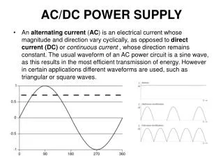
AC POWER ANALYSIS
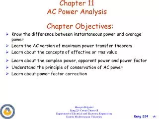
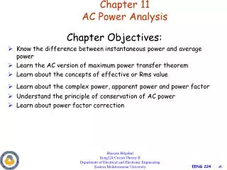
AC POWER ANALYSIS. Instantaneous & Average Power Max. Average Power Transfer RMS Value & Apparent Power Complex Power & Power Factor Correction. Instantaneous Power. Instantaneous power (in watts) : the power at any instant of time. Where:. Instantaneous Power.

AC POWER ANALYSIS
E N D
Presentation Transcript
AC POWER ANALYSIS Instantaneous & Average Power Max. Average Power Transfer RMS Value & Apparent Power Complex Power & Power Factor Correction
Instantaneous Power Instantaneous power (in watts) : the power at any instant of time Where:
Instantaneous Power The instantaneous power p(t) entering a circuit
Average Power Average Power (in watts) : the average of the instantaneous power over one period Where:
Example 1 Given that Find the instantaneous power and average power absorbed by the passive linear network. Reference : Alexander, Sadiku Chapter 11 - page 461
Exercise 1 Calculate the instantaneous power and average power if
Circuit Elements (a) Resistors: In purely resistive circuit, v and i are in phase. θv = θi. Therefore θ = 0. The average power is only dissipated in a purely resistive circuit. For a purely inductive and capacitive, the average power is zero.
Circuit Elements (b) Inductors: In purely inductive circuit, v leads by 90o, therefore θ = 90o (c) Capacitors: In purely capacitive circuit, I leads by 90o, therefore θ = - 90o
Example 2 Find the average power supplies by the source and the average power absorbed by the resistor. Reference : Alexander, Sadiku Chapter 11 - page 462
Exercise 2 Calculate the average power absorbed by the resistor and inductor. Find the average power supplies by the voltage source.
Maximum Average Power Transfer Finding the maximum average power transfer: a) circuit with a load b) the Thevenin equivalent
Maximum Average Power Transfer In rectangular form, Thevenin impedance and Load impedance: For maximum average power transfer, the load impedance ZL must be equal to the complex conjugate of the Thevenin impedance ZTh
Maximum Average Power Transfer In a situation in which the load is purely real or purely resistive load (XL=0), the load impedance (or resistance RL) is equal to the magnitude of the Thevenin impedance.
Example 3 Determine the load impedance ZL that maximizes the average power drawn from the circuit of figure below. Calculate the maximum average power. Reference : Alexander, Sadiku Chapter 11 - page 466
Exercise 3 Find the load impedance ZL that absorbs the maximum average power for the circuit of figure below. Calculate the maximum average power.
Exercise 4 In Figure below, the resistor RL is adjusted until it absorbs the maximum average power. Calculate RL and the maximum average power absorbed by it.
Effective or RMS Value The effective value of a periodic current is the dc current that delivers the same average power to a resistor as the periodic current. Finding the effective current: a) ac circuit b) dc circuit
Effective or RMS Value For any perodic function x(t) in general, the rms value is given by: The effective value of a periodic signals is its root mean square (rms) value.
Effective or RMS Value The average power can be written as: The average power absorbed by resistor R can be written as:
Example 4 Determine the rms value of the current waveform in figure below. If the current is passed through a 2Ω resistor, find the average power absorbed by the resistor. Reference : Alexander, Sadiku Chapter 11 - page 469
Exercise 5 Find the rms value of the full wave rectified sine wave in figure below. Calculate the average power dissipated in a 6Ω resistor.
Apparent Power The apparent power (in VA) is the product of the rms value of voltage and current. S is known as the apparent power.
Power Factor The power factor is the cosine of the phase difference between voltage and current. It is also the cosine of the angle of the load impedance. Power Factor : where is Power Factor Angle pf is lagging if the current lags voltage (inductive load) pf is leading if the current leads voltage (capacitive load) For purely resistive circuit, pf=1. With inductors and capacitors in the circuit, pf may reduced to less than 1.
Example 5 A series connected load draw a current when the applied voltage is Find the apparent power and the power factor of the load. Determine the element values that form the series connected load. Reference : Alexander, Sadiku Chapter 11 - page 472
Exercise 6 Calculate the power factor of the circuit below as seen by the source. What is the average power supplies by the source?
Complex Power Complex power (in VA) is the product of the rms voltage phasor and the complex conjugate of the rms current phasor. As a complex quantity, its real part is real power P and its imaginary part is reactive power Q. Complex power : VA
Complex Power Apparent power : VA Real power : W Reactive power : VAR Q = 0 for resistive loads (unity power factor) Q < 0 for capacitive loads (leading power factor) Q > 0 for inductive loads (lagging power factor)
Complex Power Power triangle Impedance triangle
Complex Power Power Triangle
Example 6 • The voltage across a load is • and the current through the element in the direction • of the voltage drop is • Find • the complex and apparent powers • the real and reactive powers • the power factor and the load impedance Reference : Alexander, Sadiku Chapter 11 - page 475
Example 7 • A load Z draws 12kVA at a power factor of 0.856 • lagging from a 120 Vrms sinusoidal source. • Calculate: • the average and reactive powers delivered to the load • the peak current • the load impedance Reference : Alexander, Sadiku Chapter 11 - page 476
Exercise 7 • A sinusoidal source supplies 10kVAR reactive • power to load • Determine: • the power factor • the apparent power delivered to the load • the peak voltage
Power Factor Correction The process of increasing the power factor without altering the voltage or current to the original load is known as power factor correction. Most loads are inductive. A load power factor is improved (to make closer to unity, pf=1) by installing a capacitor in parallel with the load. • Original inductive load b) inductive load with improved • power factor
Power Factor Correction Phasor diagram showing the effect of adding a capacitor in parallel with the inductive load
Power Factor Correction Power triangle illustrating power factor correction
Power Factor Correction Value of required shunt capacitance :
Example 8 When connected to a 120 V (rms), 60Hz power line, a load absorbs 4kW at a lagging power factor of 0.8. Find the value of capacitance necessary to raise the pf to 0.95. Reference : Alexander, Sadiku Chapter 11 - page 482
Exercise 8 Find the value of parallel capacitance needed to correct a load of 140kVAR at 0.85 lagging pf to unity pf. Assume that the load is supplied by a 110V (rms), 60Hz line.