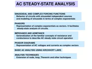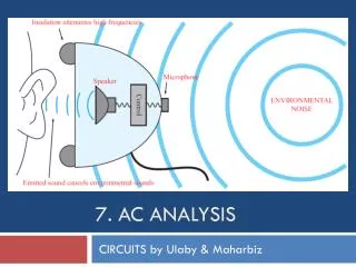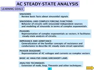
AC Network Analysis and Circuit Elements in Phasor Form
Explore capacitance, inductance, impedance in AC circuits. Understand analogies between electrical components and fluid mechanics. Learn about time-dependent signal sources and periodic waveforms. Consolidate knowledge with AC equivalent circuits and complex plane representations.

AC Network Analysis and Circuit Elements in Phasor Form
E N D
Presentation Transcript
C H A P T E R 4 AC Network Analysis
+ d _ A Parallel-plate capacitor with air gap d (air is the dielectric) A C = + d C permittivity of air = _ x _ F = 8.854 12 10 m Circuit symbol Figure 4.1 Structure of parallel-plate capacitor
C 1 C 2 C 3 1 C = 1 1 1 EQ + + C C C 1 2 3 Capacitances in series combine like resistors in parallel C C C 1 2 3 C = C + C + C EQ 1 2 3 Capacitances in parallel add Figure 4.2 Combining capacitors in a circuit
Magnetic flux lines Iron core inductor + di i ( t ) v ( t ) = L L dt L _ Circuit symbol Figure 4.8 Iron-core inductor
L 1 1 L EQ = L = L + L + L L L L L EQ 1 2 3 1 1 1 2 2 3 1 + + L L L 1 2 3 L 3 Inductances in parallel combine Inductances in series add like resistors in parallel Figure 4.9 Combining inductors in a circuit
v v 1 2 i R f q p p p p f 1 2 1 2 q f Figure 4.13 Analogy between electrical and fluid resistance R
v p 1 2 i q p f gas 2 + + P 1 C v C p f _ _ q f v p 2 1 Figure 4.14 Analogy between fluid capacitance and electrical capacitance
i L v v 1 2 + v – p I p 2 f 1 q f Figure 4.15 Analogy between fluid inertance and electrical inertance
+ + _ _ _ ( v ( t ) i ( t ) v ( t ), ) t i Generalized time-dependent sources Sinusoidal source Figure 4.18 Time-dependent signal sources
A 0 T 2 T 3 T 4 T Time Sawtooth wave A 0 T 2 T Time _ A Square wave A 0 _ T 2 T Time A Triangle wave A 0 T 2 T 3 T Time Pulse train A 0 T 2 T Time _ A Sine wave Figure 4.19 Periodic signal waveforms
T A t _ A Reference cosine T A t t _ A Arbitrary sinusoid Figure 4.20 Sinusoidal waveforms
Im j 1 sin _ 1 1 Re cos _ j e j = cos + j sin Figure 4.27 Euler’s identity
+ ~ v ( t ) i ( t ) R S – + ~ i ( t ) L v ( t ) S – + ~ v ( t ) i ( t ) C – S AC circuits Z is the impedance + ( j ) ( j ) ~ – S of each circuit element AC circuits in phasor/impedance form Figure 4.33 The impedance element
Z = R R Im L Z L Z = j L L 2 R Z Re -90 R Z C 1 1 – Z = C C j C Figure 4.34 Impedances of R, L and C in the complex plane
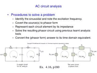
Z Z R L R L 1 1 i ( t ) x ( j ) x C ( ) R j + i ( + i v j ) Z ( ) ( j ) ( ) ( t ) t ~ t ~ 2 2 1 S – Z C – 2 S 1 R 2 A sample circuit The same circuit for AC analysis in phasor form Figure 4.42 An AC circuit
Z S + Load ~ ( j ) S – (a) Equivalent load Source Z L (b) Equivalent source Figure 4.45 AC equivalent circuits
Admittances in parallel add: Impedances in series add: Y 1 Y + Y Z Z Z + Z 1 2 1 2 1 2 Y 2 Impedances in parallel behave like resistors in parallel: Admittances in series behave like conductances in series: 1 1 1 1 Z 1 + 1 1 Z Z + 1 2 Y Y Y Y 1 2 1 2 Z 2 Figure 4.46 Rules for impedance and admittance reduction
a a Z Z 1 3 Z Z 3 1 + Z = ~ 2 S OC T – + Z Z ~ 2 L S – Z 4 b Z 4 Circuit for the computation of the Th é venin b A phasor circuit equivalent voltage with load Z Z L 2 = = O C T S Z + Z 1 2 a a Z Z Z Z 1 3 3 1 = SC N + Z Z ~ Z S 2 2 ab – Z Z 4 4 L b Circuit for the computation of the Norton Circuit for the computation of the equivalent equivalent current impedance, Z T 1 Z = Z = Z + ( Z || Z ) + Z Z + Z S ab T 3 1 2 4 3 4 = = S C N Z 1 1 1 1 + + Z Z Z + Z 1 2 3 4 Figure 4.47 Reduction of AC circuit to equivalent form