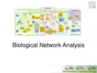
Network Analysis
This guide provides an overview of network flow analysis, focusing on the Max Flow problem. A directed connected graph consists of nodes and arcs, where the source generates flow and the sink consumes it. The Max Flow problem aims to determine the maximum flow from source to sink while adhering to capacity constraints on arcs. Notable algorithms used include the Ford-Fulkerson method and linear programming techniques. Practical examples illustrate how to find flow-augmenting paths in a network and discuss the relationship between Max Flow and Min Cut, essential for optimizing network efficiency.


Network Analysis
E N D
Presentation Transcript
Network Analysis Maxflow
What is a Network? • Directed connected graph • Source node • Sink (destination node) • Arcs are weighted (costs) • Represent a system
Maxflow problem • Determine the greatest flow through the network from Source to Sink. • Source generates flow • Sink consumes flow • Intermediate nodes only pass flow • Maximum capacity on each link
Example: Trams • Network represents tram routes • Weights are number of free places • How many people can get from A to G?
Maxflow: notations • n = the number of nodes • node 1 = Source • Node n = Sink • xij = the ammount of flow on arc from i to j • uij = capacity on arc from i to j
Algorithm • Simplex method • Take advantage of special network structure • Ford-Fulkerson labeling algorithm • Based on flow-augmenting-paths = path from source to sink whose current flow is less than its capacity.
Ford-Fulkerson labeling algorithm • Use a labeling procedure to find a flow-augmenting path. If none can be found, the current flow is optimal • Increase the current flow as much as possible in the flow-augmenting path (until some arc reaches its capacity) Goto 1.
Labeling Procedure (1) • Label the Sourcenode • For any labeled node i examine: • outgoing arcs (i,j) • incoming arcs (j,i)
Labeling Procedure (2) • Outgoing arc : label node j if the current flow is less than its capacity (uij) • Incoming arc : label node j if the incoming flow is greater than zero
Example (1) • Assume flow in all xij= 0 • Label nodes A,B,C,D and G • Find flow-augmenting path (A,D)(D,G) • Increase flow by 4 • f = 4
Example (2) • Label nodes A,B,C and E,D,F,G • Find flow-augmenting path (A,B)(B,D)(D,E)(E,G) • Increase flow by 4 • f = 8
Example (3) • Label nodes A,B,C and E,D,F,G • Find flow-augmenting path (A,D)(D,F)(F,G) • Increase flow by 2 • f = 10
Example (4) • Label nodes A,B,C,D,F and G • Find flow-augmenting path A,C,D,F,G • Increase flow by 4 • f = 14
Example (5) • Label all nodes except G • No more flow-augmenting paths! • Current flow f= 14 is optimal. • Question: Why is D labeled?
Backward Arcs (1) • Assume path 1,2,4,6 • f = 4 • The use of backward arcs is necesarry to find the max-flow! • Why?
Backward Arcs (2) • f = 8 due to backward labeling! • Flow trough backward arcs is subtracted from total flow.
Max flow – Min Cut (1) • A cut is a set of arcs that, when removed, make the Sink unreachable from Source. • Whithout a cut, there is no flow from Source to Sink. • Capacities of a cut limit the Max flow • A min-cut is a cut with minimum total capacity.
Max flow – Min Cut (2) • Ford and Fulkerson’s “Max flow-Min Cut” theorem • Max flow = Min Cut • If no flow-augmenting path can be found, it is proven that the maximum capacity of some cut is used.
Extensions to Max flow • Multiple Sources : include supersource • Multiple Sinks : include supersink • Limited Source(s) • Limited Sink(s)
Multiple Sources • Supersource connects to all sources with unrestricted capacity. • Uncapacitated links do not contibute to Min Cut!
Multiple Sinks • All Sinks connect to Supersink with unrestricted capacity • Uncapacitated links do not contribute to Min Cut!
Limited Sources/Sinks • Include supersource/sink • Place capacity on connections between supersource(s)/sink(s) and source(s)/sink(s)
Complexity of Max flow • Depends on how the flow-augmenting paths is selected. • Shortest path method: O(ne²) • Blocking flows method: O(n²e) • Preflow method: O(n³)