
SlideServe
Menu
Préférences
© SlideServe · v2026

7. AC Analysis

pia avatar
44 diapositives · 1.1K Views · Jul 19, 2014

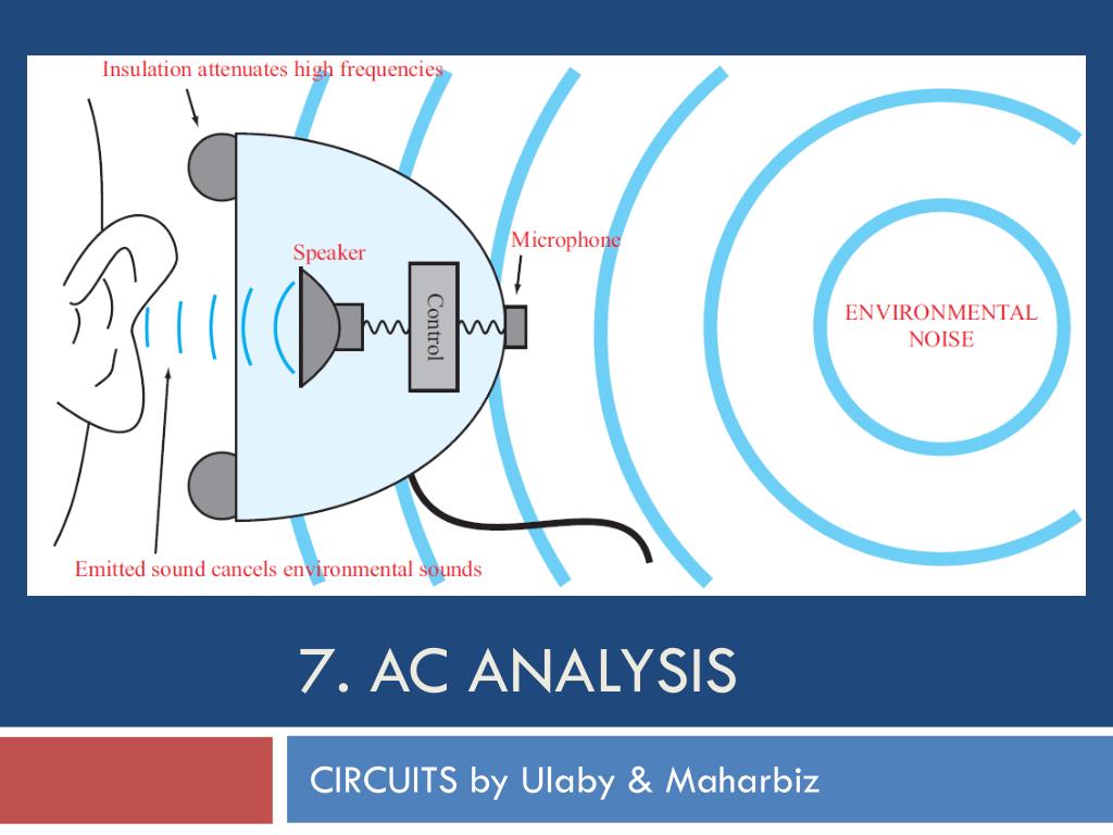
7. AC Analysis. CIRCUITS by Ulaby & Maharbiz. Overview. Linear Circuits at ac. Objective: To determine the steady state response of a linear circuit to ac signals. Sinusoidal input is common in electronic circuits
7. AC Analysis - slide 1
01 / 447. AC Analysis
1 / 17

Télécharger la présentation

7. AC Analysis
Une image / un lien ci-dessous est fourni (tel quel) pour télécharger la présentation

Politique de téléchargement : le contenu du site vous est fourni TEL QUEL pour votre information et votre usage personnel ; il ne peut être vendu, concédé sous licence ni partagé sur d’autres sites sans l’accord de son auteur.Le contenu vous est fourni TEL QUEL, pour votre information et votre usage personnel uniquement. Téléchargez la présentation en cliquant sur ce lien. Lors du téléchargement, si vous ne parvenez pas à télécharger une présentation, l’éditeur a peut-être supprimé le fichier de son serveur.Pendant le téléchargement, si vous ne parvenez pas à obtenir une présentation, le fichier a peut-être été supprimé par l’éditeur.

F I N

Plus de contenu associé

Transcription de la présentation
  1. 7. AC Analysis CIRCUITS by Ulaby & Maharbiz

  2. Overview

  3. Linear Circuits at ac Objective:Todetermine the steady state response of a linear circuit to ac signals • Sinusoidal input is common in electronic circuits • Any time-varying periodic signal can be represented by a series of sinusoids (Fourier Series) • Time-domain solution method can be cumbersome

  4. Sinusoidal Signals Useful relations

  5. Phase Lead/Lag

  6. Complex Numbers We will find it is useful to represent sinusoids as complex numbers Rectangular coordinates Polar coordinates Relations based on Euler’s Identity

  7. Relations for Complex Numbers Learn how to perform these with your calculator/computer

  8. Phasor Domain 1. The phasor-analysis technique transforms equations from the time domain to the phasor domain. 2. Integro-differential equations get converted into linear equations with no sinusoidal functions. 3. After solving for the desired variable--such as a particular voltage or current-- in the phasor domain, conversion back to the time domain provides the same solution that would have been obtained had the original integro-differential equations been solved entirely in the time domain.

  9. Phasor Domain Phasor counterpart of

  10. Time and Phasor Domain It is much easier to deal with exponentials in the phasor domain than sinusoidal relations in the time domain. You just need to track magnitude/phase, knowing that everything is at frequency w.

  11. Phasor Relation for Resistors Current through a resistor Time domain Time Domain Frequency Domain Phasor Domain

  12. Phasor Relation for Inductors Current through inductor in time domain Time domain Phasor Domain Time Domain

  13. Phasor Relation for Capacitors Voltage across capacitor in time domain is Time domain Time Domain Phasor Domain

  14. Summary of R, L, C

  15. ac Phasor Analysis General Procedure Using this procedure, we can apply our techniques from dc analysis

  16. Example 1-4: RL Circuit Cont.

  17. Example 1-4: RL Circuit cont.

  18. Resistor Inductor Capacitor Impedance and Admittance Impedance is voltage/current Admittance is current/voltage R = resistance = Re(Z) G = conductance = Re(Y) X = reactance = Im(Z) B = susceptance = Im(Y)

  19. Impedance Transformation

  20. Voltage & Current Division

  21. Cont.

  22. Example 7-6: Input Impedance (cont.)

  23. Example 7-9: Thévenin Circuit

  24. Linear Circuit Properties Thévenin/Norton and Source Transformation Also Valid

  25. Phasor Diagrams

  26. Phase-Shift Circuits

  27. Example 7-11: Cascaded Phase Shifter Solution leads to:

  28. Node 1 Cont.

  29. (cont.) Cont.

  30. (cont.)

  31. Example 7-14: Mesh Analysis by Inspection

  32. Example 7-16: Thévenin Approach

  33. Example 7-16: Thévenin Approach (Cont.)

  34. Example 7-16: Thévenin Approach (Cont.)

  35. Power Supply Circuit

  36. Ideal Transformer

  37. Half-Wave Rectifier

  38. Full-Wave Rectifier Current flow during first half of cycle Current flow during second half of cycle

  39. Smoothing RC Filter

  40. Complete Power Supply

  41. Example 7-20: Multisim Measurement of Phase Shift

  42. Example 7-20 (cont.) Using Transient Analysis

  43. Summary