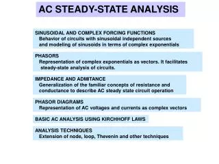
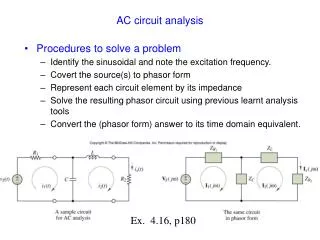
STEADY STATE AC CIRCUIT ANALYSIS
STEADY STATE AC CIRCUIT ANALYSIS. Introduction. Previously we have analyzed circuits with time-independent sources – voltage and current that do not change with time DC circuit analysis .

STEADY STATE AC CIRCUIT ANALYSIS
E N D
Presentation Transcript
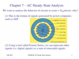
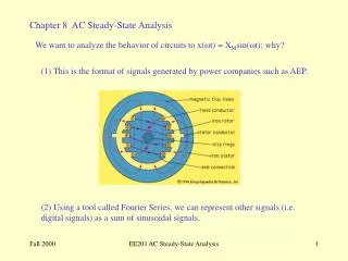
Introduction Previously we have analyzed circuits with time-independent sources – voltage and current that do not change with time DC circuit analysis In this section we will analyze circuits containing time-dependent sources – voltage and current vary with time One of the important classes of time-dependent signal is the periodic signals x(t) = x(t +nT), where n = 1,2 3, … and T is the period of the signal
t t t t Introduction Typical periodic signals normally found in electrical engineering: Sawtooth wave Square wave Triangle wave pulse wave
t Introduction In SEE 1003 we will deal with one of the most important periodic signal of all :- sinusoidal signals Signals that has the form of sine or cosine function
Introduction In SEE 1003 we will deal with one of the most important periodic signal of all :- sinusoidal signals Signals that has the form of sine or cosine function Circuit containing sources with sinusoidal signals (sinusoidal sources) is called an AC circuit. Our analysis will be restricted to the steady state behavior of AC circuit.
Why do we need to study sinusoidal AC circuit ? • Dominant waveform in the electric power industries worldwide – household and industrial appliations • ALL periodic waveforms (e.g. square, triangular, sawtooth, etc) can be represented by sinusoids • You want to pass SEE1003 !
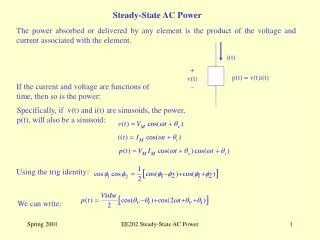
v(t) t 2 3 4 Sinusoidal waveform Let a sinusoidal signal of a voltage is given by: v(t) = Vm sin (t) Vm Vm – the amplitude or maximum value – the angular frequency (radian/second) t – the argument of the sine function
The voltage can also be written as function of time: v(t) = Vm sin (t) v(t) t T/2 T (3/2)T 2T Sinusoidal waveform Let a sinusoidal signal of a voltage is given by: v(t) = Vm sin (t) Vm
The voltage can also be written as function of time: v(t) = Vm sin (t) v(t) Vm t T/2 T (3/2)T 2T Sinusoidal waveform Let a sinusoidal signal of a voltage is given by: v(t) = Vm sin (t) • In T seconds, the voltage goes through 1 cycle T is known as the period of the waveform • In 1 second there are 1/T cycles of waveform • The number of cycles per second is the frequency f The unit for f is Hertz
A more general expression of a sinusoidal signal is v1(t) = Vm sin (t + ) v(t) Vm t Sinusoidal waveform is called the phase angle, normally written in degrees Let a second voltage waveform is given by: v2(t) = Vm sin (t - ) v1(t) = Vm sin (t + ) v2(t) = Vm sin (t - )
v(t) v1(t) = Vm sin (t + ) v2(t) = Vm sin (t - ) Vm t Sinusoidal waveform
v(t) v1(t) = Vm sin (t + ) v2(t) = Vm sin (t - ) Vm t Sinusoidal waveform v1 and v2 are said to be out of phase v1 is said to be leading v2 by (-) or ( + ) alternatively, v2 is said to be lagging v1 by (-) or ( + )
v(t) Vm t Sinusoidal waveform Some important relationships in sinusoidals Vm sin (t) -Vm sin (t)
v(t) Vm 180o t Sinusoidal waveform Some important relationships in sinusoidals Vm sin (t) -Vm sin (t)
v(t) 180o t Sinusoidal waveform Some important relationships in sinusoidals -Vm sin (t) Therefore, Vmsin (t 180o) = -Vmsin (t )
v(t) t Vm Sinusoidal waveform Some important relationships in sinusoidals Vmsin (t) = Vmsin (t 360o) Therefore, Vmsin (t + ) = Vmsin (t + 360o) Vmsin (t + )= Vmsin (t (360o )) e.g., Vmsin (t + 250o) = Vmsin (t (360o 250o)) = Vm sin (t 110o) 250o 110o
Sinusoidal waveform Some important relationships in sinusoidals It is easier to compare two sinusoidal signals if: • Both are expressed sine or cosine • Both are written with positive amplitudes • Both have the same frequency
Sinusoidal waveform Average and effective value of a sinusoidal waveform An average value a periodic waveform is defined as: e.g. for a sinusoidal voltage,
Ieffec Vdc R i(t) v(t) R Sinusoidal waveform Average and effective value of a sinusoidal waveform An effective value or Root-Mean-Square (RMS) a periodic current (or voltage) is defined as: The value of the DC current (or voltage) which, flowing through a R-ohm resistor delivers the same average power as does the periodic current (or voltage) Power to be equal: Average power: (absorbed) Average power: (absorbed)
Sinusoidal waveform Average and effective value of a sinusoidal waveform For a sinusoidal wave, RMS value is : or
Phasors A phasor: A complex number used to represent a sinusoidal waveform. It contain the information about the amplitude and phase angle of the sinusoid. In steady state condition, the sinusoidal voltage or current will have the same frequency. The differences between sinusoidal waveforms are only in the magnitudes and phase angles Why used phasors ? Analysis of AC circuit will be much more easier using phasors
cos is the real part of sin is the imaginary part of Imaginary Real v(t) = This can be written as Phasors How do we transform sinusoidal waveforms to phasors ?? Phasor is rooted in Euler’s identity: Supposed v(t) = Vm cos (t + )
v(t) = Phasors How do we transform sinusoidal waveforms to phasors ??
= = v(t) = phasor transform v(t) = Vmcos (t +) v(t) = Phasors How do we transform sinusoidal waveforms to phasors ?? is the phasor transform of v(t)
va(t) = Vmcos (t -) i(t) = Imcos (t +) vx(t) = Vmcos (t + - 90o) vx(t) = Vmsin (t +) Phasors Polar forms We will use these notations Rectangular forms Some examples ….
Im Re Phasors Polar forms We will use these notations Rectangular forms Phasors can be graphically represented using Phasor Diagrams
Im Re Phasors Polar forms We will use these notations Rectangular forms Phasors can be graphically represented using Phasor Diagrams
Phasors Polar forms We will use these notations Rectangular forms Phasors can be graphically represented using Phasor Diagrams Draw the phasor diagram for the following phasors:
phasor transform • va(t) = Vmcos (t -) inverse phasor transform v(t) = Vmcos (t + ) Phasors To summarize … • If v1(t), v2(t), v3(t), v4(t), ….vn(t) are sinusoidals of the same frequency and v(t) = v1(t) + v2(t) + v3(t) + v4(t) + ….+vn(t) , in phasors this can be written as: V = V1 + V2 + V3 +V4 + …+Vn • It is also possible to do the inverse phasor transform:
R iR IR Phasor Relationships for R, L and C The relationships between V and I for R, L and C are needed in order for us to do the AC circuit analysis + VR + vR If iR = Im cos (t + i) vR = R (Im cos (t + i)) vR and iR are in phase !
L iL IL Phasor Relationships for R, L and C The relationships between V and I for R, L and C are needed in order for us to do the AC circuit analysis + VL + vL If iL = Im cos (t + i) vL = L (Im (-sin (t + i))) vL = L (Im cos (t + I +90o)) vL leads iL by 90o !
C ic Ic Phasor Relationships for R, L and C The relationships between V and I for R, L and C are needed in order for us to do the AC circuit analysis + Vc + vc If vc = Vm cos (t + v) ic = C (Vm( -sin (t + v))) ic = C (Vm cos (t + v +90o)) ic leads vc by 90o !