AC STEADY-STATE ANALYSIS
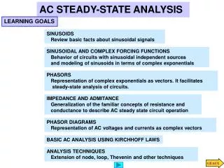
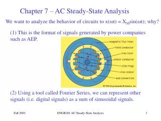
AC STEADY-STATE ANALYSIS. SINUSOIDAL AND COMPLEX FORCING FUNCTIONS Behavior of circuits with sinusoidal independent sources and modeling of sinusoids in terms of complex exponentials. PHASORS Representation of complex exponentials as vectors. It facilitates

AC STEADY-STATE ANALYSIS
E N D
Presentation Transcript
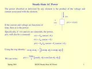
AC STEADY-STATE ANALYSIS SINUSOIDAL AND COMPLEX FORCING FUNCTIONS Behavior of circuits with sinusoidal independent sources and modeling of sinusoids in terms of complex exponentials PHASORS Representation of complex exponentials as vectors. It facilitates steady-state analysis of circuits. IMPEDANCE AND ADMITANCE Generalization of the familiar concepts of resistance and conductance to describe AC steady state circuit operation PHASOR DIAGRAMS Representation of AC voltages and currents as complex vectors BASIC AC ANALYSIS USING KIRCHHOFF LAWS ANALYSIS TECHNIQUES Extension of node, loop, Thevenin and other techniques
algebraic problem SINUSOIDAL AND COMPLEX FORCING FUNCTIONS If the independent sources are sinusoids of the same frequency then for any variable in the linear circuit the steady state response will be sinusoidal and of the same frequency Determining the steady state solution can be accomplished with only algebraic tools!
SOLVING A SIMPLE ONE LOOP CIRCUIT CAN BE VERY LABORIOUS IF ONE USES SINUSOIDAL EXCITATIONS TO MAKE ANALYSIS SIMPLER ONE RELATES SINUSOIDAL SIGNALS TO COMPLEX NUMBERS. THE ANALYSIS OF STEADY STATE WILL BE CONVERTED TO SOLVING SYSTEMS OF ALGEBRAIC EQUATIONS ... … WITH COMPLEX VARIABLES If everybody knows the frequency of the sinusoid then one can skip the term exp(jwt)
SHORTCUT 1 NEW IDEA: PHASORS ESSENTIAL CONDITION ALL INDEPENDENT SOURCES ARE SINUSOIDS OF THE SAME FREQUENCY BECAUSE OF SOURCE SUPERPOSITION ONE CAN CONSIDER A SINGLE SOURCE THE STEADY STATE RESPONSE OF ANY CIRCUIT VARIABLE WILL BE OF THE FORM SHORTCUT 2: DEVELOP EFFICIENT TOOLS TO DETERMINE THE PHASOR OF THE RESPONSE GIVEN THE INPUT PHASOR(S)
It is essential to be able to move from sinusoids to phasor representation Example Phasors can be combined using the rules of complex algebra The phasor can be obtained using only complex algebra We will develop a phasor representation for the circuit that will eliminate the need of writing the differential equation
Phasor representation for a resistor PHASOR RELATIONSHIPS FOR CIRCUIT ELEMENTS RESISTORS Phasors are complex numbers. The resistor model has a geometric interpretation The voltage and current phasors are colineal In terms of the sinusoidal signals this geometric representation implies that the two sinusoids are “in phase”
Relationship between sinusoids Example For the geometric view use the result INDUCTORS The relationship between phasors is algebraic The voltage leads the current by 90 deg The current lags the voltage by 90 deg
Relationship between sinusoids CAPACITORS The relationship between phasors is algebraic In a capacitor the current leads the voltage by 90 deg The voltage lags the current by 90 deg
(INPUT) IMPEDANCE (DRIVING POINT IMPEDANCE) IMPEDANCE AND ADMITTANCE For each of the passive components the relationship between the voltage phasor and the current phasor is algebraic. We now generalize for an arbitrary 2-terminal element The units of impedance are OHMS Impedance is NOT a phasor but a complex number that can be written in polar or Cartesian form. In general its value depends on the frequency
KVL AND KCL HOLD FOR PHASOR REPRESENTATIONS In a similar way, one shows ... The components will be represented by their impedances and the relationships will be entirely algebraic!!
LEARNING EXAMPLE SPECIAL APPLICATION: IMPEDANCES CAN BE COMBINED USING THE SAME RULES DEVELOPED FOR RESISTORS
SKETCH THE PHASOR DIAGRAM FOR THE CIRCUIT CAPACITIVE CASE INDUCTIVE CASE PHASOR DIAGRAMS Display all relevant phasors on a common reference frame Very useful to visualize phase relationships among variables. Especially if some variable, like the frequency, can change Any one variable can be chosen as reference. For this case select the voltage V
LEARNING EXAMPLE DO THE PHASOR DIAGRAM FOR THE CIRCUIT 2. PUT KNOWN NUMERICAL VALUES It is convenient to select the current as reference Read values from diagram! 1. DRAW ALL THE PHASORS
BASIC ANALYSIS USING KIRCHHOFF’S LAWS PROBLEM SOLVING STRATEGY For relatively simple circuits use For more complex circuits use
ANALYSIS TECHNIQUES PURPOSE: TO REVIEW ALL CIRCUIT ANALYSIS TOOLS DEVELOPED FOR RESISTIVE CIRCUITS; I.E., NODE AND LOOP ANALYSIS, SOURCE SUPERPOSITION, SOURCE TRANSFORMATION, THEVENIN’S AND NORTON’S THEOREMS. 1. NODE ANALYSIS
Circuit with voltage source set to zero (SHORT CIRCUITED) SOURCE SUPERPOSITION = Circuit with current source set to zero(OPEN) Due to the linearity of the models we must have Principle of Source Superposition + The approach will be useful if solving the two circuits is simpler, or more convenient, than solving a circuit with two sources We can have any combination of sources. And we can partition any way we find convenient
Thevenin Equivalent Circuit for PART A THEVENIN’S EQUIVALENCE THEOREM
Voltage Divider 5. THEVENIN ANALYSIS
Frequency domain SOURCE 2: FREQUENCY 20r/s Principle of superposition EXAMPLE Find the current i(t) in steady state The sources have different frequencies! For phasor analysis MUST use source superposition
LEARNING BY DESIGN USING PASSIVE COMPONENTS TO CREATE GAINS LARGER THAN ONE PRODUCE A GAIN=10 AT 1KhZ WHEN R=100