
AC/DC POWER SUPPLY
E N D
Presentation Transcript
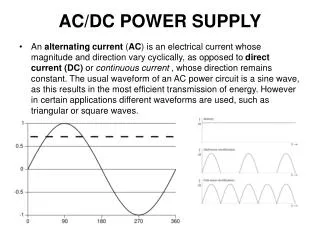
AC/DC POWER SUPPLY • An alternating current (AC) is an electrical current whose magnitude and direction vary cyclically, as opposed to direct current (DC) or continuous current , whose direction remains constant. The usual waveform of an AC power circuit is a sine wave, as this results in the most efficient transmission of energy. However in certain applications different waveforms are used, such as triangular or square waves.
AC/DC: What's the Difference? In 1887 direct current (DC) was king. At that time there were 121 Edison power stations scattered across the United States delivering DC electricity to its customers. But DC had a great limitation -- namely, that power plants could only send DC electricity about a mile before the electricity began to lose power. So when George Westinghouse introduced his system based on high-voltage alternating current (AC), which could carry electricity hundreds of miles with little loss of power, people naturally took notice. A "battle of the currents" ensued. In the end, Westinghouse's AC prevailed. The American Experience | Edison's Miracle of Light | AC - DC: What's the Difference?
The amplitude of AC An AC voltage v can be described mathematically as a function of time by the following equation: Vpeak is the peak voltage (unit: volt), ω is the angular frequency (unit: radians per second) The angular frequency is related to the physical frequency, f, which represents the number of oscillations per second (unit = hertz), by the equation ω =
How to compare AC and DC • AC voltage is usually expressed as a root mean square (RMS) value, written Vrms. For a sinusoidal voltage: Vrms is useful in calculating the power consumed by a load. If a DC voltage of VDC delivers a certain powerP into a given load, then an AC voltage of Vpeak will deliver the same average power P into the same load if Vrms = VDC. Because of this fact, RMS is the normal means of measuring AC voltage. 110VAC is actually the RMS value which is used from the energy companies in America. But the voltage peak value is 155.55V.
AC/DC POWER SUPPLY Block-Diagramm
AC/DC POWER SUPPLY Circuit diagram : Note: This configuration applies for 230V (Europe).
Transformer: • Function: A transformer is a device used to increase (step up) or decrease (step down) the AC voltage in a circuit. • Properties: Laminated in order to reduce power losses through Eddy Currents. • Operation: The way transformers operate is based on the principle that an alternating current in the primary coil will induce an alternating electro-magnetic-field (EMF) on the secondary coil due to their mutual inductance.
Whatishappeninginsidea transformer? 1. Iron Core molecules before energizing. 2. Energizing the coil and thus magnetic flux generation. 3. Iron Core molecules line up after energizing.
Rectifier: Diode Ideal Diode RealDiode
Full Wave Rectifier: Link to PDF with the bridge rectifier animation • One disadvantage of the full-wave rectifier is that there is a voltage loss of 1.4V across the diodes.
You could either build a full wave rectifier bridge out of 4 diodes (i.e. 1N4001 capable of 50V and 1A) or an already made rectifier as the one shown below: While the full-wave rectifier is an improvement on the half-wave rectifier, its output still isn't suitable as a power supply for most circuits since the output voltage still varies between 0V and Vs-1.4V. So, if you input 12V AC, you will get 10.6V DC output. This is why the 'smoothing' block, described in the next chapter is required.
Smoothing: Vr • Where: I [Amps], C [F], f [Hz] and Vr [V] • Note: The ripple voltage shouldn't be higher than 10% of Vs.
Ex 1: What should be the Capacitance to appropriately smooth an 24Vpp AC signal, 60Hz and 1A? Ex 2: How big would the Ripple voltage be if the current gets reduced to 500mA? • Compromise: • Availability of components • Price of components • Ripple voltage Q3: What factors affect the amount of ripple?
Regulation: • Reason: While there are many circuits that will tolerate a smoothed power supply, some must have a completely regular supply with no ripple voltage. If the ripple voltage is too large and the input voltage to the regulator falls below the regulated voltage of the regulator, then of course the regulator will not be able to produce the correct regulated voltage. As a rule of thumb the input voltage to a regulator should usually be at least 2V above the regulated voltage.
By using the brochures of the components all the requirements can be found.


![G7 - PRACTICAL CIRCUITS [2 exam question - 2 groups]](https://cdn2.slideserve.com/3713677/g7-practical-circuits-2-exam-question-2-groups-dt.jpg)


![G7 - PRACTICAL CIRCUITS [3 exam question - 3 groups]](https://cdn3.slideserve.com/7086572/g7-practical-circuits-3-exam-question-3-groups-dt.jpg)