Download
1 / 13
140 likes | 254 Vues
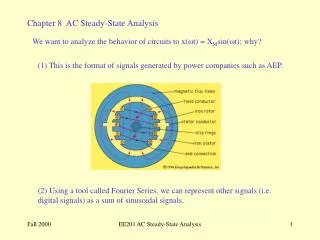
Understand key concepts in AC power analysis, including instantaneous vs. average power, power factor correction, and the impact of current magnitude on power transmission systems. Practice problem solving for power factor correction. Learn about the measurement of power using wattmeters. Enhance your knowledge of power systems engineering.

E N D
Chapter 11AC Power Analysis Chapter Objectives: • Know the difference between instantaneous power and average power • Learn the AC version of maximum power transfer theorem • Learn about the concepts of effective or Rms value • Learn about the complex power, apparent power and power factor • Understand the principle of conservation of AC power • Learn about power factor correction Huseyin Bilgekul Eeng224 Circuit Theory II Department of Electrical and Electronic Engineering Eastern Mediterranean University
Power Factor Correction • The design of any power transmission system is very sensitive to the magnitude of the current in the lines as determined by the applied loads. • Increased currents result in increased power losses (by a squared factor since P = I2R) in the transmission lines due to the resistance of the lines. • Heavier currents also require larger conductors, increasing the amount of copper needed for the system, and they require increased generating capacities by the utility company. • Since the line voltage of a transmission system is fixed, the apparent power is directly related to the current level. • In turn, the smaller the net apparent power, the smaller the current drawn from the supply. Minimum current is therefore drawn from a supply when S = P and QT = 0. • The process of introducing reactive elements to bring the power factor closer to unity is called power-factor correction. Since most loads are inductive, the process normally involves introducing elements with capacitive terminal characteristics having the sole purpose of improving the power factor.
Power Factor Correction Increasing the power factor without altering the voltage or current to the load is called Power Factor Correction Inductive Load with improved power factor correction Original Inductive Load Effect of capacitor on total current Power triangle of power factor correction
Power Factor Correction Qc = Q1 – Q2 = P (tan θ1 - tan θ2) = ωCVrms2 Q2 = P tan θ2 P = S1 cos θ1 • Increasing the power factor without altering the voltage or current to the load is called Power Factor Correction. Q1 = S1 sin θ1 = P tan θ1
Power Factor Correction • The process of increasing the power factor without altering the voltage or current to the original load is called power factor correction. • Power factor correction is necessary for economic reasons. • The capacitance value needed to change the pf angle from 1 to 2. • Similarly the inductance value needed to change the pf angle from 1 to 2 for a capacitive load.
Practice Problem 11.15: Find the value of the capacitance needed to correct a load of 140 kVAR at 0.85 lagging pf to unity pf. The load is supplied by a 110 Volt (rms), 60 Hz line.
ApplicationsPower Measurement Wattmeter is the instrument for measuring the average power. Two coils are used, the high impedance Voltage coil and the low impedance Current coil. Wattmeter measures the average power given by: Wattmeter Wattmeter connected to the load