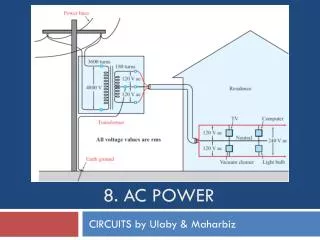
AC Power
AC Power. Learning Objectives. Define real (active) power, reactive power and average power. Calculate the real and reactive power in AC series parallel networks.


AC Power
E N D
Presentation Transcript
Learning Objectives • Define real (active) power, reactive power and average power. • Calculate the real and reactive power in AC series parallel networks. • Graph the real and reactive power of purely resistive, inductive, or capacitive loads in AC series parallel networks as a function of time. • Determine when power is dissipated, stored, or released in purely resistive, inductive, or capacitive loads in AC series parallel networks. • Calculate the total real and total reactive power consumed in AC series parallel networks.
DC Power • Power is the measure of work per unit time, or joules/sec or watts.
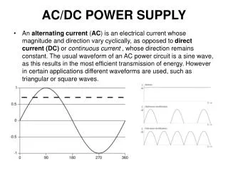
AC Power to a Resistive Load • In ac circuits, voltage and current are functions of time. • Power at a particular instant in time is given • This is called instantaneous power.
Average Power to a Resistive Load • p is always positive • All of the power delivered by the source is absorbed by the load. • Average power P = VmIm/2
Average Power to a Resistive Load • Using RMS values V and I • P is called real power or active power because it is really dissipated by the load. • Active power is the average value of instantaneous power.
Consider the following circuit where i = Imsin t . Can we write an expression instantaneous power or pL(t) ? Power to an Inductive Load
p is equally positive and negative. All of the power delivered by the source is returned. Average power PL = 0 W Power to an Inductive Load
Reactive Power • Instantaneous power to an inductive load is given by pL= VI sin 2 t • The product VI is called reactive power and given the symbol QL. • The unit of QL is VAR (volt-amps reactive)
Reactive Power • Reactive power is the portion of power that flows into load and then back out. • It contributes nothing to average power. • The power that flows into and out of a pure inductor is reactive power only.
Example Problem 1 For each circuit, determine real and reactive power.
Consider the following circuit where i = Imsin t . Can we write an expression instantaneous power or pC(t) ? Power to a Capacitive Load
p is equally positive and negative All of the power delivered by the source is returned (no power losses with a pure reactive load). Average power PC = 0 W Power to a Capacitive Load
Reactive Power • Instantaneous power to an capacitive load is given by pL= -VI sin 2 t • The product VI is called reactive power and given the symbol QC. • The unit of QC is VAR (volt-amps reactive) • By convention, reactive power due to capacitance is defined as negative.
Example Problem 2 Determine real and reactive power.
AC Power to a Resistive LoadAC Power to a Inductive LoadAC Power to a Capacitive Load
Power • Reactive components only store/discharge power, they do not dissipate it. • The power dissipated is entirely due to the resistive component of impedance.
Total Power in AC Circuits • The total power real (PT) and reactive power (QT) is simply the sum of the real and reactive power for each individual circuit elements. • How elements are connected does not matter for computation of total power.
Total Power in AC Circuits • Sometimes it is useful to redraw the circuit to symbolically express the real and reactive power loads
Example Problem 3 For the RC circuit below, determine XC. If frequency is 60 Hz, determine C.
Example Problem 4 For the RC circuit below, determine PT and QT.If frequency is 60 Hz, determine C.