DC-AC Power Inverter
400 likes | 717 Vues
DC-AC Power Inverter . Design II, Spring 2004 Midterm Presentation. Team Members . Min-Chiat Wee Team Leader. Daniel Martin. Faculty Advisor Dr. Yaroslav Koshka. Dustin Bailey. Industrial Advisor: Dr. Mark Kinsler. Jason Horner. Abstract.

DC-AC Power Inverter
E N D
Presentation Transcript
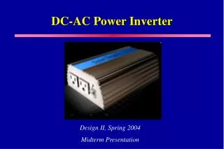
DC-AC Power Inverter Design II, Spring 2004 Midterm Presentation
Team Members Min-Chiat Wee Team Leader Daniel Martin Faculty Advisor Dr. Yaroslav Koshka Dustin Bailey Industrial Advisor: Dr. Mark Kinsler Jason Horner
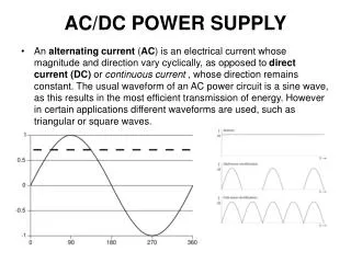
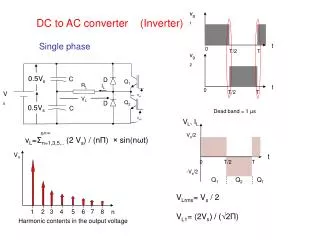
Abstract • Design a switch-mode power supply that converts 12 VDC to 120 VAC • Pure sinusoidal waveform with 60 Hz frequency • 300 W continuous output
Problem Statement • Problems: • Inexpensive inverters are very inefficient due to a high harmonic content of the output signal • Pure sine wave inverters have a high cost per watt ratio • Solution: • An inexpensive inverter that produces a near perfect sine wave output
Main Components 12 VDC Input (from vehicle battery) PWM Control Circuit Half-bridge Converter Transformer Low-pass Filter Full-bridge Inverter Sinusoidal PWM Controller 120 VAC, 60 Hz, 300 W Output
PWM Control Circuit 12 VDC Input (from vehicle battery) PWM Control Circuit Half-bridge Converter Transformer Low-pass Filter Full-bridge Inverter Sinusoidal PWM Controller 120 VAC, 60 Hz, 300 W Output
PWM Controller • Produces two complementary pulses to control half-bridge transistors • Problem: • Voltage dropped less than 170VDC when the input voltage was decreased • Solution: • A feedback network was added for voltage regulation
PWM Oscilloscope Waveform Prototype Device as Built
Half-bridge Converter 12 VDC Input (from vehicle battery) PWM Control Circuit Half-bridge Converter Transformer Low-pass Filter Full-bridge Inverter Sinusoidal PWM Controller 120 VAC, 60 Hz, 300 W Output
Half-bridge Converter • Chops the 12 VDC to produce a 12 V, 100 kHz, square pulse • Problem: • IRF740A MOSFETs has an Rds(on) = 0.55Ω, resulting in high power losses. • Solution: • Chose IRF530 MOSFETs with an Rds(on) = 0.16 Ω
Half-bridge Oscilloscope Readings Prototype Device As Built
Transformer 12 VDC Input (from vehicle battery) PWM Control Circuit Half-bridge Converter Transformer Low-pass Filter Full-bridge Inverter Sinusoidal PWM Controller 120 VAC, 60 Hz, 300 W Output
Step Up Transformer • Steps up voltage from 12 VAC to 340 VAC • Problem: • Initial transformer had high internal capacitance leading to failure of device • Solution: • Custom ordered a transformer to fit our design constraints
DC-DC Converter Testing Device As Built Simulation
Sinusoidal PWM Controller 12 VDC Input (from vehicle battery) PWM Control Circuit Half-bridge Converter Transformer Low-pass Filter Full-bridge Inverter Sinusoidal PWM Controller 120 VAC, 60 Hz, 300 W Output
Sinusoidal PWM Circuit • Last Semester: • PIC18F452 – too many unused ports • Insufficient dead-time in PIC program caused cross-conduction in full-bridge inverter • This Semester: • Chose PIC18F252 – fewer unused ports • Programmed 500ns between each control pulse
Initialize all variables Count0 = 300 (300 duty cycles) 300 duty cycle values? One Sampling Period? Output 1 = high, Output 2 = low Read duty cycle table (increment pointer) Duty cycle and sampling period timer Output 1 = low, Output 2 = high Decrement Count0 by 1 Has duty cycle been reached? Software Flow Diagram yes no no yes no yes
Sinusoidal PWM Drive Pulses Device As Built Simulation
Full-bridge Inverter 12 VDC Input (from vehicle battery) PWM Control Circuit Half-bridge Converter Transformer Low-pass Filter Full-bridge Inverter Sinusoidal PWM Controller 120 VAC, 60 Hz, 300 W Output
Full-bridge Inverter • Converts 170 VDC to a 120 Vrms, 60 Hz, sine wave • IRF740A MOSFETs • Vdss = 400 V • Id = 10 A • Rds(on) = 0.55 Ω
Simulation vs. Actual (unfiltered) Simulation Device As Built
60 Hz 60 Hz 18 kHz 18 kHz Frequency Spectrum Before Filtering Simulation Device As Built
Low-pass Filter 12 VDC Input (from vehicle battery) PWM Control Circuit Half-bridge Converter Transformer Low-pass Filter Full-bridge Inverter Sinusoidal PWM Controller 120 VAC, 60 Hz, 300 W Output
Low-pass Filter • 2nd order L-C filter • Filters to retain a 60 Hz fundamental frequency • Few components • Handle current • Wind inductor (fine tune)
Final Output Testing Simulation Prototype
Frequency Spectrum After Filtering Simulation Device As Built
PCB Layout Dimensions: 7.5” x 6.5” x 2.5”
Status and Goals • Continue working with PCB • Fine tune filter • Improve packaged appearance • Attempt to further reduce costs
Acknowledgements • Dr. Yaraslov Koshka • Dr. Mark Kinsler • Dr. Mike Mazzola • Dr. Raymond Winton • Dr. Herb Ginn • Jim Gafford • Robin Kelley • Len Cox • Jessie Thomas
Any Questions? ???