LCDTV AC/DC Power range
470 likes | 852 Vues
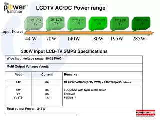
LCDTV AC/DC Power range. 20” LCD TV. 32” LCD TV. 37” LCD TV. 40” LCD TV. 14” LCD TV. 26” LCD TV. Input Power. 44 W 70W 140W 180W 195W 285W. 300W input LCD-TV SMPS Specifications. AHB TOPOLOGY. Asymmetric control half bridge converter.

LCDTV AC/DC Power range
E N D
Presentation Transcript
LCDTV AC/DC Power range 20” LCD TV 32” LCD TV 37” LCD TV 40” LCD TV 14” LCD TV 26” LCD TV Input Power 44 W 70W 140W 180W 195W 285W 300W input LCD-TV SMPS Specifications
AHB TOPOLOGY • Asymmetric control half bridge converter
Full load measurement Board size:170mmx215mm, Height:35mm
Attachment: 1.ML4800/FAN4800 2.FAN7382 3.FAN5234 4.FSDM311 5.FSCQ0765 Rev 1.1
ML4800: Average Current Sense Vin Isense IGainmod
ML4800/FAN4800 Continuous Mode • Peak to RMS ratio lower: Lower I2R losses • Ripple current: Lower core losses • Lower EMI: Smaller input filter • Requires very fast boost diode
ML4800/FAN4800 A High Performance PFCAverage Current,CCM ML4800/ML4824
ML4800/FAN4800 A More Detail Circuit…
ML4800/FAN4800 Gain Modulator---(I) • Gain Modulator: Generate the reference current wave-form. • IAC Input: rectified AC input sine wave Decides the “Shape” of the current Reference • VEAO Input: Vo Decides the “Size” of the current Reference to regulate the Vo. • VRMS Input: RMS AC line voltage Feed-forward the 1 / Vin(rms)2 to speed up the response & maintain a constant loop gain.
ML4800/FAN4800 Gain Modulator---(II) Vin Isense IGainmod Vin↑2Vin, then Isense↑2Isense,=>Pin↑4Pin => Vout ↑↑. So it is necessary for a RMS AC line voltage feed forward to make Isense ↓0.5Isense while Vin↑2Vin.
ML4800/FAN4800 Gain Modulator---(III) • IGAINMOD = GAIN * IAC • = K * (VEAO- 0.625 )* IAC , K is in units of V-1 • K is a function of VRMS-2 . Left is the K/ VRMS curve Average line voltage compensation with brownout control * the K of the curve is in units of m V-1
ML4800/FAN4800 Gain Modulator---(IV) • Continuous mode PFC controllers modify the gain error in the control loop • For voltages in the range 85V to 220V, the gain curve compensates for the Vrms dependency • Without this compensation, the gain of the control loop would be directly proportional to Vrms2 • For voltages below 85V, the gain curve provides brownout protection Modulator compensates for effect of loop gain increase with VIN(RMS)2 with piecewise linear curve
ML4800/FAN4800: “Slew Enhanced” Error Amp Improves Transient Response VFB • Special shaped, non-linear gain error amplifiers are used. • Such that under steady-state operating conditions the transconductance of the error amplifier is at a local minimum. • Lower gain to get higher PF when in Steady State. • Higher gain to get fast transient response
ML4800/FAN4800 VFB (Pin 15) Tri-Fault Detect • Should VFB go too low (* Pin 15 < 0.5 V ), too high (* Pin 15 > 2.75 V), or open, the internal Tri-Fault Detect circuit will senses the error and terminates the PFC output driver.
ML4800/FAN4800 Switching Frequency Setting(Pin7) ML4824-1:fpwm=fpfc ML4824-2: fpwm=2fpfc ML4800:fpwm=fpfc fpfc≈ 1/ (0.51* RT CT )
ML4800/FAN4800 Vin OK Comparator • The Vin OK Comparator monitors the DC output of the PFC and inhibit the PWM if the voltage on the VFB is less than 2.45 V. Once this voltage reaches over 2.45 V, the soft-start of the PWM section begins.
ML4800/FAN4800 PWM Soft Start (Pin 5) --- (I) • Chose Css = tDELAY * (25 uA/1.25V) Where Css is the soft start Cap. tDELAY is the desired Start- up delay. • During the tDELAYonly the PFC works. PWM does not work. After then, the duty of the PWM O/P begins to (gradually) expand to its normal condition.
ML4800/FAN4800 RAMP 2 (Pin 8) --- (III)Voltage Mode (1)--- No Feed-forward
ML4800/FAN4800 RAMP 2 (Pin 8) --- (IV)Voltage Mode (2)--- with Feed-forward Ramp
ML4800/FAN4800 DC ILIMIT (Pin 9) • the DC ILIMIT input is used for output stage overcurrent protection.
ML4800/FAN4800 PFC/PWM Combo Controllers • Combine: Leading edge PFC and trailing edge PWM in one package • PFC turn off, then PWM turn on, at the same instant to minimize • the momentary “no-load” period, thus lowering ripple voltage generated by the switching action. PWM switch PFC switch
FAN4800 The FAN4800 is a controllers for power factor corrected, switched mode power supplies. Power Factor Correction (PFC) enables the use of smaller, lower cost bulk storage capacitors, reduces power line loading, and reduces stress on the components of a switched mode power supply. • Average Current Mode • 23V BiCMOS Process • Vcc OVP, Brown out, UVLO, Soft start • Low Power Detect Comparator • More Precise Spec. for OVP, OCP, Tri-Fault • Low Power Consumption : 100uA, 3mA • 16-pin Solution
FSC HVIC Solution • Fairchild Semiconductor. • High Side only • FAN7360(250/500mA,600V) • Half bridge • FAN7380(60/130mA),7382(250/500mA,600V), • 7385(2/2A,600V),7386(3/3A,600V),FAN7387(6/6A,600V) • 3-phase • FAN7390(250/500mA,600V) • Self oscillation
Power Solutions – Switching Regulators for Point of Load Applications Vin New Product 24V FAN5234/6 1f FAN 5240 2f FAN2105* 12V FAN5182 (Controller 1-3f) + FAN5009 (Driver) Legend 5V FAN5307 FAN2001* FAN20112012 FAN2003* FAN6520A Integrated Switcher (Controller+Driver+MOSFET) Integrated Controller (Controller+Driver) New Products 3.3V Stand-alone Controller (Controller+ External Driver) Iout 0.3A 1A 3A 5A 20A 40A 60A 100A 120A 140A * -- Sampling Now
GND DRAIN Vcc DRAIN Vfb DRAIN NC Vstr FSDM311 • Features • BCDMOS controller + Strong Avalanche CFET • Built in Start up Circuit • Internal soft-start circuit • Peak current limit • New 8DIP PKG for wide creepage • Target Application • FSDM311 • Max 8watt Charger with universal input range • Max 20watt auxiliary P/S for PC with 220V input 8DIP
Built-in Start up V s t r D r a i n 6 , 7 , 8 5 U V L O < 7 V V c c 2 V o l t a g e I n t e r n a l U V L O R e f . B i a s U V L O > 9 V Voltage Mode Control V c k S e n s e F E T O S C D R I V E R 5 u A 4 0 0 u A P W M S Q V f b 3 R S / S L E B 1 0 m S Soft Start Protection O C P V t h 4 . 5 V R s e n s e R e s e t O L P O V P S Q Peak Current Limit R M i n . 2 1 V T S D / 4 H i s 4 0 Auto Restart G N D 4 1 NC Block Diagram of FSDM311
Features and Advantages of FSCQ-series Green FPSTM • Features • - Optimized for Quasi-resonant converter (Low EMI and High Efficiency) • - Fully avalanche rated and 100% tested SenseFET • - Pulse-by-pulse current limiting • - Improved reliability through various protection functions • : Over voltage, Over load, Over current, Thermal shutdown • - Advanced Burst operationfor low power consumption in standby (<1W) • - Internal Soft start function (20ms) • - Extended Quasi-resonantoperation for wide operation range • - Reduced startup and operating currents • Advantages • - Reduced board space (simple & compact circuit design) • - Decreased assembly time and field failure rate Enhanced productivity TO-220F-5L 1. Introduction to FPS
FSCQ-series Functional Block Diagram QRC Control Burst Mode Operation SenseFET OLP Current Mode Control AOCP TSD OVP Auto Restart Mode Latch Mode
FSCQNormal Quasi-Resonant Switching at heavy load • Advantages • Reduced switching noise (Low EMI) • Improved efficiency • Removed RCD snubber • Limitations • Intermittent switching at light load due to relatively large LEB time
FSCQExtended Quasi-Resonant Switching at light load • Advantages • Guarantee stable operation over wide load range • Improve efficiency at light load condition
FSCQAdvanced Soft-Start • - Internal soft start (20ms) • - For a fast output build up, offset is introduced in the soft start 85V input 265V input
FSCQAdvanced Burst Operation • Drop output voltage to below half (any level) to minimize the loss caused by leakage current in the high voltage output • Reduce the effective switching frequency to minimize switching loss • Reduce the FPS operating current in the burst operation
FSCQAdvanced Burst Operation Vi=85Vac Vi=265Vac 1. Vds 2. Vcc 3. Vfb 4. Id
FSCQ/KA5Q Lists Protection Option – OLP(Over Load Protection), OCL(Over Current Latch), OVP(Over Voltage Protection), TSD(Thermal Shutdown) (1) Open Frame Pin(max) Test Condition : Flyback Converter, Discontinuous Current Mode, Dmax=0.5, Vin(dc)=100V