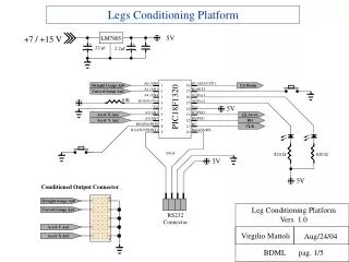
Legs Conditioning Platform
This modular conditioning platform enables data acquisition from strain gauges and accelerometers, specifically the Straight Gauge An0 and Curved Gauge An1. Each gauge and accelerometer provides conditioned outputs. The platform utilizes PIC18F1320 microcontroller, LM7805 voltage regulator, and MAX5154 DACs to ensure accurate measurement and control. With RS232 communication at 9600bps, users can send commands for starting/stopping data acquisition, setting DAC voltages, and performing auto-zero functions. This flexible design supports multiple input configurations and reference voltages.

Legs Conditioning Platform
E N D
Presentation Transcript
1 18 2 17 3 16 4 15 PIC18F1320 5V LM7805 5 14 6 13 22mf 2.2mf 7 12 8 11 9 10 Straight Gauge An0 CS Strain A0 /AN0 B3 /AN1/CCP1 Curved Gauge An1 A1 /AN1 B2/INT2 10K A4 /AN4 A7/Osc1 A6/Osc2 MCLR/RA5/Vpp 5V VSS VDD Accel. X An2 CS Accel. A2/AN2 B7/PGD Accel. Y An3 DO A3/AN3 B6/PGC CLK B0/AN4/INT0 B5 B1/AN5/TXINT1 B4/AN6/RX 100 nf 820Ω 820Ω 5V 5V Conditioned Output Connector 9 Straight Gauge An0 Leg Conditioning Platform Vers. 1.0 Curved Gauge An1 + + RS232Connector Accel. Y An2 Virgilio Mattoli Aug/24/04 Accel. X An3 1 BDML pag. 1/5 Legs Conditioning Platform +7 / +15 V
5V 5V Refernce Voltage 10K LM6152(1/2) LM6152 (1/2) 5V X 10 X 10 10K Ref AMPs Ref DACs Leg Input Connector 5V 1 CurvedInput Accel. X Input 9 Straight Input _ _ Accel. Y Input 5V 5V + + MAX 5154 MAX 5154 DAC 1 1 16 16 2 2 15 15 Straight DAC OutPut Accel. X DAC OutPut Curved DAC OutPut Accel. Y DAC OutPut 3 3 14 14 5V 5V 4 4 13 13 Ref DACs Ref DACs Ref DACs Ref DACs 5 5 12 12 10K 10K 6 6 11 11 CS Strain CS Accel. 7 7 10 10 DO DO 8 8 9 9 CLK CLK Leg Conditioning Platform Vers. 1.0 DAC Virgilio Mattoli Aug/24/04 BDML pag. 2/5 Legs Conditioning Platform 100nf
5V Straight Input Straight DAC OutPut Straight Gauge An0 1,5K Ref AMPs 220nf 5V 5V AD623 AD623 AD623 AD623 Accel. Y Input CurvedInput Accel. Y DAC OutPut Curved DAC OutPut Curved Gauge An1 Accel. Y An2 1,5K 1,5K Ref AMPs Ref AMPs 1 Rg 1 Rg 1 Rg 1 Rg Rg 8 Rg 8 Rg 8 Rg 8 220nf 220nf 2 In - 2 In - 2 In - 2 In - Vdd 7 Vdd 7 Vdd 7 Vdd 7 3 In + 3 In + 3 In + 3 In + Out 6 Out 6 Out 6 Out 6 4 Vss 4 Vss 4 Vss 4 Vss Ref 5 Ref 5 Ref 5 Ref 5 5V Accel. X An3 Leg Conditioning Platform Vers. 1.0 Accel. X Input Accel. X DAC OutPut 1,5K Virgilio Mattoli Aug/24/04 Ref AMPs 220nf BDML pag. 3/5 Legs Conditioning Platform 156 Ω G = X 642 156 Ω G = X 642 25K G = X 5 25K G = X 5
PC-TX PC-RX PC-GND MAX233 T2in R2out 1 20 T1in R2in 2 19 R1out T2out 3 18 1 2 3 4 5 R1in V- 4 17 T1out C2- 5 16 Serial RS232 DB9 Connector (Female) 6 7 8 9 GND C2+ 6 15 Vcc V+ 7 14 C1+ C1- PIC Tx 8 13 GND V- PIC Rx 9 12 C2- C2+ Gnd 10 11 5V (In) Leg Conditioning Platform Vers. 1.0 Virgilio Mattoli Aug/24/04 BDML pag. 4/5 Legs Conditioning Platform RS 232 CABLE To RS232Connector
Leg Conditioning Platform Vers. 1.0 Virgilio Mattoli Aug/24/04 BDML pag. 5/5 Legs Conditioning Platform RS232 REMOTE CONTROL Connection with standard RS232 protocol: 9600kbps, 1 stop bit, No handsk Command PC -> Device ASCII Chr “9” = 57 = START Acquisition Data ASCII Chr “8” = 56 = STOP Acquisition Data ASCII Chr “5” = 53 = Autozero Gauges ASCII Chr “6” = 54 = Autozero Accelerometers ASCII Chr “0” = 48 = Set DAC Straight Gauge = 2.5V ASCII Chr “1” = 49 = Set DAC Curve Gauge = 2.5V ASCII Chr “2” = 50 = Set DAC X Acc = 2.5V ASCII Chr “3” = 51 = Set DAC Y Acc = 2.5V Device -> Command PC When received START command, device send acquired value for Gauges and Accelerometers: Each value is four digit in hexadecimal representation (the first oneis ever equal to zero), ranging form 0x0000 = 0V to 0X03FF = 5V . The values are separated by tabulation (9 in ASCII).Each acquisition is separated by a carriage return (13, 10 in ASCII) The order of rows is:Straight gauge value – TAB – Curve gauge value – TAB – Acc X value – TAB – Acc Y value – CR The acquisition can be done configuring in suitable way the the Windows HyperTerminal