Download
1 / 40
430 likes | 949 Vues
College Physics Chapter 4 DYNAMICS: FORCE AND NEWTON’S LAWS OF MOTION PowerPoint Image Slideshow. Figure 4.1. Newton’s laws of motion describe the motion of the dolphin’s path. (credit: Jin Jang). Figure 4.2.

E N D
College Physics Chapter 4 DYNAMICS: FORCE AND NEWTON’S LAWS OF MOTION PowerPoint Image Slideshow
Figure 4.1 • Newton’s laws of motion describe the motion of the dolphin’s path. (credit: Jin Jang)
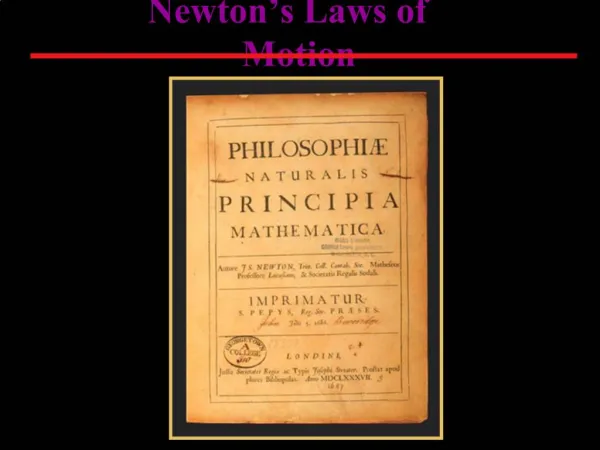
Figure 4.2 • Issac Newton’s monumental work, PhilosophiaeNaturalis Principia Mathematica, was published in 1687. It proposed scientific laws that are still used today to describe the motion of objects. (credit: Service commun de la documentation de l'Université de Strasbourg)
Figure 4.3 • Part (a) shows an overhead view of two ice skaters pushing on a third. Forces are vectors and add like other vectors, so the total force on the third skater is in the direction shown. In part (b), we see a free-body diagram representing the forces acting on the third skater.
Figure 4.4 • The force exerted by a stretched spring can be used as a standard unit of force. (a) This spring has a length x when undistorted. (b) When stretched a distance Δx, the spring exerts a restoring force, Frestore , which is reproducible. (c) A spring scale is one device that uses a spring to measure force. The force Frestoreis exerted on whatever is attached to the hook. Here Frestore has a magnitude of 6 units in the force standard being employed.
Figure 4.5 • Different forces exerted on the same mass produce different accelerations. • Two children push a wagon with a child in it. Arrows representing all external forces are shown. The system of interest is the wagon and its rider. The weight w of the system and the support of the ground N are also shown for completeness and are assumed to cancel. The vector f represents the friction acting on the wagon, and it acts to the left, opposing the motion of the wagon. • All of the external forces acting on the system add together to produce a net force, Fnet. The free-body diagram shows all of the forces acting on the system of interest. The dot represents the center of mass of the system. Each force vector extends from this dot. Because there are two forces acting to the right, we draw the vectors collinearly. • A larger net external force produces a larger acceleration ( a′ > a ) when an adult pushes the child.
Figure 4.6 • The same force exerted on systems of different masses produces different accelerations. • A basketball player pushes on a basketball to make a pass. (The effect of gravity on the ball is ignored.) • The same player exerts an identical force on a stalled SUV and produces a far smaller acceleration (even if friction is negligible). • The free-body diagrams are identical, permitting direct comparison of the two situations. A series of patterns for the free-body diagram will emerge as you do more problems.
Figure 4.7 • The net force on a lawn mower is 51 N to the right. At what rate does the lawn mower accelerate to the right?
Figure 4.8 • A sled experiences a rocket thrust that accelerates it to the right. Each rocket creates an identical thrust T . As in other situations where there is only horizontal acceleration, the vertical forces cancel. The ground exerts an upward force N on the system that is equal in magnitude and opposite in direction to its weight, w . The system here is the sled, its rockets, and rider, so none of the forces between these objects are considered. The arrow representing friction ( f ) is drawn larger than scale.
Figure 4.9 • When the swimmer exerts a force Ffeeton wall on the wall, she accelerates in the direction opposite to that of her push. This means the net external force on her is in the direction opposite to Ffeeton wall . This opposition occurs because, in accordance with Newton’s third law of motion, the wall exerts a force Fwallon feet on her, equal in magnitude but in the direction opposite to the one she exerts on it. The line around the swimmer indicates the system of interest. Note that Ffeeton wall does not act on this system (the swimmer) and, thus, does not cancel Fwall on feet . Thus the free-body diagram shows only Fwall on feet , w , the gravitational force, and BF, the buoyant force of the water supporting the swimmer’s weight. The vertical forces w and BF cancel since there is no vertical motion.
Figure 4.10 • A professor pushes a cart of demonstration equipment. The lengths of the arrows are proportional to the magnitudes of the forces (except for f , since it is too small to draw to scale). Different questions are asked in each example; thus, the system of interest must be defined differently for each. System 1 is appropriate for Example 4.4, since it asks for the acceleration of the entire group of objects. Only Ffloor and f are external forces acting on System 1 along the line of motion. All other forces either cancel or act on the outside world. System 2 is chosen for this example so that Fprof will be an external force and enter into Newton’s second law. Note that the free-body diagrams, which allow us to apply Newton’s second law, vary with the system chosen.
Figure 4.12 • The person holding the bag of dog food must supply an upward force Fhandequal in magnitude and opposite in direction to the weight of the food w . • The card table sags when the dog food is placed on it, much like a stiff trampoline. Elastic restoring forces in the table grow as it sags until they supply a force N equal in magnitude and opposite in direction to the weight of the load.
Figure 4.13 • Since motion and friction are parallel to the slope, it is most convenient to project all forces onto a coordinate system where one axis is parallel to the slope and the other is perpendicular (axes shown to left of skier). N is perpendicular to the slope and f is parallel to the slope, but w has components along both axes, namely w⊥ and w ∥ . N is equal in magnitude to w⊥ , so that there is no motion perpendicular to the slope, but f is less than w ∥ , so that there is a downslope acceleration (along the parallel axis).
Figure 4.14 • An object rests on an incline that makes an angle θ with the horizontal.
Figure 4.15 • When a perfectly flexible connector (one requiring no force to bend it) such as this rope transmits a force T , that force must be parallel to the length of the rope, as shown. The pull such a flexible connector exerts is a tension. Note that the rope pulls with equal force but in opposite directions on the hand and the supported mass (neglecting the weight of the rope). This is an example of Newton’s third law. The rope is the medium that carries the equal and opposite forces between the two objects. The tension anywhere in the rope between the hand and the mass is equal. Once you have determined the tension in one location, you have determined the tension at all locations along the rope.
Figure 4.16 • Tendons in the finger carry force T from the muscles to other parts of the finger, usually changing the force’s direction, but not its magnitude (the tendons are relatively friction free). • The brake cable on a bicycle carries the tension T from the handlebars to the brake mechanism. Again, the direction but not the magnitude of T is changed.
Figure 4.17 • The weight of a tightrope walker causes a wire to sag by 5.0 degrees. The system of interest here is the point in the wire at which the tightrope walker is standing.
Figure 4.18 • When the vectors are projected onto vertical and horizontal axes, their components along those axes must add to zero, since the tightrope walker is stationary. The small angle results in T being much greater than w .
Figure 4.19 • We can create a very large tension in the chain by pushing on it perpendicular to its length, as shown. Suppose we wish to pull a car out of the mud when no tow truck is available. Each time the car moves forward, the chain is tightened to keep it as nearly straight as possible. The tension in the chain is given by sin (θ) ;since θ is small, T is very large. This situation is analogous to the tightrope walker shown in Figure 4.17, except that the tensions shown here are those transmitted to the car and the tree rather than those acting at the point where F⊥ is applied.
Figure 4.20 • Unless an infinite tension is exerted, any flexible connector—such as the chain at the bottom of the picture—will sag under its own weight, giving a characteristic curve when the weight is evenly distributed along the length. Suspension bridges—such as the Golden Gate Bridge shown in this image—are essentially very heavy flexible connectors. The weight of the bridge is evenly distributed along the length of flexible connectors, usually cables, which take on the characteristic shape. (credit: Leaflet, Wikimedia Commons)
Figure 4.22 • A sketch of Tarzan hanging from a vine. • Arrows are used to represent all forces. T is the tension in the vine above Tarzan, FT is the force he exerts on the vine, and w is his weight. All other forces, such as the nudge of a breeze, are assumed negligible. • Suppose we are given the ape man’s mass and asked to find the tension in the vine. We then define the system of interest as shown and draw a free-body diagram. FT is no longer shown, because it is not a force acting on the system ofinterest; rather, FT acts on the outside world. • Showing only the arrows, the head-to-tail method of addition is used. It is apparent that T = - w , if Tarzan is stationary.
Figure 4.23 • A view from above of two tugboats pushing on a barge. • The free-body diagram for the ship contains only forces acting in the plane of the water. It omits the two vertical forces—the weight of the barge and the buoyant force of the water supporting it cancel and are not shown. Since the applied forces are perpendicular, the x- and y-axes are in the same direction as Fxand Fy. The problem quickly becomes a one-dimensional problem along the direction of Fapp, since friction is in the direction opposite to Fapp.
Figure 4.24 • A traffic light is suspended from two wires. • Some of the forces involved. • Only forces acting on the system are shown here. The free-body diagram for the traffic light is also shown. • The forces projected onto vertical (y) and horizontal (x) axes. The horizontal components of the tensions must cancel, and the sum of the vertical components of the tensions must equal the weight of the traffic light. • The free-body diagram shows the vertical and horizontal forces acting on the traffic light.
Figure 4.25 • The various forces acting when a person stands on a bathroom scale in an elevator. The arrows are approximately correct for when the elevator is accelerating upward—broken arrows represent forces too large to be drawn to scale. T is the tension in the supporting cable, w is the weight of the person, wsis the weight of the scale, we is the weight of the elevator, Fs is the force of the scale on the person, Fp is the force of the person on the scale, Ft is the force of the scale on the floor of the elevator, and N is the force of the floor upward on the scale. • The free-body diagram shows only the external forces acting on the designated system of interest—the person.
Figure 4.26 • The electric force field between a positively charged particle and a negatively charged particle. When a positive test charge is placed in the field, the charge will experience a force in the direction of the force field lines.
Figure 4.27 • The exchange of masses resulting in repulsive forces. • The person throwing the basketball exerts a force Fp1 on it toward the other person and feels a reaction force FB away from the second person. • The person catching the basketball exerts a force Fp2 on it to stop the ball and feels a reaction force F′B away from the first person. • The analogous exchange of a meson between a proton and a neutron carries the strong nuclear forces Fexch and F′exch between them. An attractive force can also be exerted by the exchange of a mass—if person 2 pulled the basketball away from the first person as he tried to retain it, then the force between them would be attractive.
Figure 4.28 • The world’s largest particle accelerator spans the border between Switzerland and France. Two beams, traveling in opposite directions close to the speed of light, collide in a tube similar to the central tube shown here. External magnets determine the beam’s path. Special detectors will analyze particles created in these collisions. Questions as broad as what is the origin of mass and what was matter like the first few seconds of our universe will be explored. This accelerator began preliminary operation in 2008. (credit: Frank Hommes)
Figure 4.29 • Space-based future experiments for the measurement of gravitational waves. Shown here is a drawing of LISA’s orbit. Each satellite of LISA will consist of a laser source and a mass. The lasers will transmit a signal to measure the distance between each satellite’s test mass. The relative motion of these masses will provide information about passing gravitational waves. (credit: NASA)
Figure 4.30 • A leg is suspended by a traction system in which wires are used to transmit forces. Frictionless pulleys change the direction of the force T without changing its magnitude.
Figure 4.34 • A baby is weighed using a spring scale.
Figure 4.36 • An overhead view of the horizontal forces acting on a child’s snow saucer sled.
Figure 4.38 • Braces are used to apply forces to teeth to realign them. Shown in this figure are the tensions applied by the wire to the protruding tooth. The total force applied to the tooth by the wire, Fapp , points straight toward the back of the mouth.
Figure 4.39 • Superhero and Trusty Sidekick hang motionless on a rope as they try to figure out what to do next. Will the tension be the same everywhere in the rope?
Figure 4.40 • Achilles tendon
Figure 4.41 • The force T2 needed to hold steady the person being rescued from the fire is less than her weight and less than the force T1 in the other rope, since the more vertical rope supports a greater part of her weight (a vertical force).