Front Tracking
Front Tracking. Tutorial Lectures by James Glimm with thanks to the Front Tracking team S. Dutta, E. George, J. Grove, H. Jin, Y. Kang, M.-N. Kim,T. Lee, X.-L. Li, T. Liu, X.-F. Liu, A. Marchese, W. Oh, A. Pamgemanan, R. Samulyak, D. S. Sharp, Z. Xu, Y. Yu,Y. Zhang, M. Zhao, N. Zhao

Front Tracking
E N D
Presentation Transcript
Front Tracking Tutorial Lectures by James Glimm with thanks to the Front Tracking team S. Dutta, E. George, J. Grove, H. Jin, Y. Kang, M.-N. Kim,T. Lee, X.-L. Li, T. Liu, X.-F. Liu, A. Marchese, W. Oh, A. Pamgemanan, R. Samulyak, D. S. Sharp, Z. Xu, Y. Yu,Y. Zhang, M. Zhao, N. Zhao at BNL, LANL, Univ. Stony Brook
Outline of Presentation • Overview • Basic idea of Front Tracking • Advantages and disadvantages of Front Tracking • Modular software design • Use and availability of software • Technical Description • Geometry: interfaces and the description of free surface • Grid free and grid based formulations • Physics: fronts and the propagation of states and points • Advanced Topics • Conservative and nonconservative formulations • Ongoing Research
Part I: Overview -- The Basic Ideas • Front is a lower dimensional grid, moving through the volume filling grid • Key ideas are • the geometrical description of the front • the algorithm to propagate it • the modification of the finite difference stencils which cross the front so that the stencils see only states on one side of the front • Front tracking is the ultimate ALE code as it is pure Eulerian except for a lower dimensional Lagrangian surface grid • Beyond ALE: front tracking has built in slide surfaces for interfaces (shear discontinuity allowed)
Conservative Equations for Front Tracking Hyperbolic: Track discontinuities in U Elliptic: Track discontinuities in Parabolic: Mixed: any or all of the above in different subsystems of equations
Front Tracking:Advantages and Disadvantages • Advantages: • Often gives the best solutions on coarser grids compared to other methods for problems with important discontinuity interfaces • Solves interface problems not solvable by other methods • Disadvantages: • For shocks: too complex relative to benefits • Not well suited to diffused or spread out fronts • Software complexity implies learning period for use
Three Examples • Code comparison and grid convergence study for spherical implosions and explosions: shock passage through an interface (the spherical Richtmyer-Meshkov problem) • Code comparisons for a single mode accelerated interface (the planar 2D Rayleigh-Taylor problem) • Code comparison for 3D steady acceleration of a density discontinuity interface (the planar Rayleigh-Taylor problem)
Tracked (left) and untracked (right) spherical implosions, 200x200 grids
Comparison of L1 error for contact for tracked and untracked simulations
Single mode Rayleigh-Taylor instability comparison (20 cells across): Frontier, Tracked TVD, TVD
Fluid Mixing Simulation Early time FronTier simulation of Late time FronTier simulation of a 3D RT mixing layer. 3D RT mixing layer.
Comparison of Simulation, Theory, Experiments penetration distance of light fluid into heavy 0.05 -- 0.077 (Experiment) 0.05 -- 0.06 (Theory) 0.07 (Simulation - tracked) 0.035 (Simulation - TVD untracked) 0.06 (Simulation - TVD untracked, diffusion renormalized)
FronTier and TVD Simulations without / with diffusion remormalization
Density at Z = const. Cross section. Comparison of FronTier (left) and TVD (right)
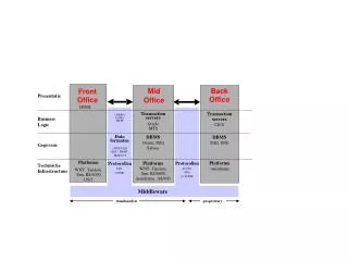
Modular Code Design • Interface library: Describes geometry of an interface. This is at the level of nonmanifold geometry, meaning that the interface surfaces can intersect on curves, which can meet at points. • Typical support routines: make_object, print, read_print, copy, delete, modify where object = point, bond, curve, triangle, surface, interface • Higher level support routines: test for intersections, find side or closest interface point or component from a general position in space, glue pieces for parallel communication
Modular Code Design • Front Library: Describes Interface with physical states (at this level, a unit of storage) • Typical support routines: Propagation of interface points; re-meshing of interface points • Hyp Library: Assembles stencils for explicit solution of hyperbolic equations. • Gas: Provides Riemann solvers to Front and finite difference stencil operators to Hyp. • EOS: Contains constitutive laws to close equations Reference: J. Glimm, J. Grove, X.-L. Li, K-M. Shyue, Q. Zhang, Y. Zeng. “Three Dimnsionslal Front Tracking.” SISC 19 (1998), 703-707
Software Availability • Interface -- geometrical routines • Freely available • Hyperbolic tracking -- finite difference for fronts and for interior states near fronts • Available by request • Plans to make this portion into freely available library • Elliptic and parabolic tracking -- finite elements for elliptic operators with discontinuous coefficients • Available by request • Physics libraries -- Gas, MHD, Solid, Porous media http://www.ams.sunysb.edu/~FronTier.Ftmain.html
Part II: Technical Description • Geometry: interfaces and the description of free surfaces • Grid free and grid based formulations • Conservative, higher order formulation • Interface operations and support • Untangle, remesh • Dynamics: fronts and the propagation of states and points • Local and nonlocal Riemann solvers • Interior difference solvers near a tracked front • Parallel communication (and AMR) • repatch pieces of fronts after parallel communication
II.1: GeometryThe front separates space into connected components, each with possibly different physics
Interface data structures Coords: (pointer to) three numbers in a 3D space Point: coords, left state, right state Bond: point for each end, and pointers to next, prev bond Node: beginning/end of curve. This is a curve with a list of incoming and outgoing curves Curve: doubly linked list of bonds, starting and ending at a node, pointers to first/last bond, start/end node Tri: three points for vertices and pointers to neighbors
Interface data structures Surface: defined by bounding curves and by linked tris Hypersurface element: tri in 3D, bond in 2D Hypersurface: surface in 3D, curve in 2D. Left/right component index Interface: has all of the above
Elementary Interface Operations • For each object (POINT, BOND, CURVE, TRI, SURFACE, INTERFACE): • allocate, install, copy, print, read_print, delete, next (iterators) • For parallel communication: • communicate in blocks • reset all pointers in communicated blocks • reconnect interface patches communicated near edges or over buffer zones at edges
Advanced Interface Operations • Test for intersections • Resolve intersections (untangle) • Locate relative to interface • which side, or connected component • closest interface point • Determine crossings of interface with lines • to define finite difference stencil • to define grid based reconstruction • Precomputation (hash tables) for efficiency
Grid free vs. Grid based • Grid free: interface and interior (volume) grid share a comon length scale but are otherwise unrelated • Grid based: the interface is directly tied to the volume grid. • The interface is defined by its intersections with the grid cell edges. • It is assumed that each grid cell edge has at most one intersection with the interface. • In the interior of the cell, the interface is reconstructed from its cell edge crossings.
Grid free vs. Grid based • Grid free • can be more accurate • is less robust • Grid based • highly robust • Lorensen and Cline. “Marching Cubes”. Computer Graphics, 21 (1987), 163-169. • Hybrid: alternate grid free and grid based at some frequency • robust since grid based is used as a backup • improved interface description • best of three algorithms
Grid-based interface reconstruction:14 nonisomorphic cases in 3D
References for Interface Construction J. Glimm and O. McBryan, “A Computational Model for Interfaces”, Adv. Appl. Math. 6 (1985), 422-435 J. Glimm, J. W. Grove, X.-L. Li, K.-M. Shyue, Q. Zhang snd Y. Zeng, “Three Dimensional Front Tracking”, SIAM J. Sci. Comp. 19 (1998), 703-727. J. Glimm, J. W. Grove, X.-L. Li and D. Tan, “A Robust Computational Algorithm for Dymanic Interface Tracking in Three Dimensions”, SIAM J. Sci. Comp. 21 (2000), 2240- 2256. J. Glimm, J. W. Grove, X. L.Li and D. C. Tan “Robust Computational Algorithms for Dymanic Interface Tracking in Three Dimaneions”, SIAM J. Sci. Comp. 21 (2000) 2240-2256.
Redistribution of points on a curve will ensure equal spacing and provide some smoothing
Grid free redistribute in 3D is based on elementary triangle operations
3D redistribution improves the triangle quality for the surface
Grid based redistribution The grid based algorithm is automatically redistributed every step. The algorithm is based on reconstruction of the interface from the crossings of the interface with the grid cell edges. The reconstruction can be viewed as a special type of redistribution.
Grid free untangle 1. Test all triangle pairs for intersections (use hash table) 2. Find (cross) bonds defined by intersecting trinagles 3. Link cross bonds to form cross curves 4. Install cross curves into interface, cutting surfaces along line of intersection 5. Test for and remove unphysical surfaces 6. Remove unneeded cross curves 2D algorithm: just the analogues of 1+2+6 needed
Grid-based topological correctionThe same construction works for 3D. Untangle is an elementary step for grid based tracking.
Grid based reconstruction (includes redistribute and untangle) 1 Determine the crossings of the interface with the cell block edges 2. Determine the components at the corners of the cell block. This is done, starting with a point not swept by the interface (thus with the same component as the previous time step), and followed by a walk through all mesh block squares. Double crossings and other unphysical crossings are eliminated at this step. 3. Reconstruct the interface, using the one of the 14 nonisomorphic templates which matches the give cell 4. Check for and resolve any possible inconsistency at each cell face
Grid based matching at cell faces On cell faces, the interface is also grid based, in the sense that it is determined by reconstruction with the intersections of the interface with the edges of that face. Thus two cells with a common face share a boundary with common data (edge intersections) and a common solution (the reconstruction). Thus the interface is consistent across adjacent cells after reconstruction (it is watertight). Exception: 4 edge crossings for a single face allow a nonunique reconstruction, and an explicit watertight patch is needed. Uniqueness of reconstruction matching is important for parallel communication.
Propagation of Points and States • Front points (each point has a left and right side state) • Normal propagate: solution of a nonlocal Riemann problem in one dimension • Tangential propagate: project surface onto tangent plane and apply finite differences there • Interior points • Many different finite difference methods supported. No modification in case the stencil does not cross the front • Use of ghost cells to reconstruct stencil states in case the stencil crosses the front
Algorithms for differencing with multi-components defined by fronts The only routine which sees multicomponents is the Riemann solver. The Riemann solver will accept left and right states describing possibly different physics (e.g. a different Equation of State). Its solution defines the coupling or boundary conditions between these two regimes. All other routines (finite differences, interpolation, finite elements, tangential front update) see only states from one component at a time. In this way there is no numerical mass diffusion across a front.
The interface motion is split into normal and tangential steps
Three steps in the normal propagation algorithm Determine states at new point via characteristic equations. Solve RP at new point to get left and right states. Repropagate point using average of t0 and t 0+ t velocities to achieve higher order accuracy
A Solution Function Evaluation of the solution at the foot of a backwards characteristic will fall at an arbitrary point relative to the grid. A solution function is provided to evaluate the solution at an arbitrary point. It is based on interpolation from (regular) grid data points using bilinear interpolation and from front points using linear interpolation on triangles