HYDRODYNAMICS
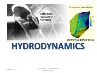
WATER FLOW ON CAVITATING PROPELLER. HYDRODYNAMICS. COMPUTING DRAG FORCES. HYDRODYNAMICS. Fluid is in motion: there is relative motion between layers and hence, viscous forces in the fluid and drag forces on solid surfaces are to be considered

HYDRODYNAMICS
E N D
Presentation Transcript
WATER FLOW ON CAVITATING PROPELLER HYDRODYNAMICS COMPUTING DRAG FORCES KK's FLM 221: Week8: Introd. to Hydrodynamics
HYDRODYNAMICS • Fluid is in motion: there is relative motion between layers and hence, viscous forces in the fluid and drag forces on solid surfaces are to be considered • Hydrodynamics is a most applicable form of Fluid Mechanics as all objects move in fluids, and many designs in nature and engineering have to use its laws and relationships e.g. the heart, the kidneys, pumps, aeroplanes, refrigerators, cyclones, Tsunamis etc! • Each particle has own motion but general motion is superimposed on it. The resultant motion creates a specific path for the particle. This path is called a PATH LINE. (Question:why own motion? Where does it originate from?) • General motion of all the particles follows a general sense of direction in line with the pressure drop and the constraining solid boundary. The general sense of direction is the direction of the velocity of the particles. It traces out STREAM LINES. (Question:From this statement, what drives the motion and what limits it?) • Particles past a specific point or area map out a path or region after some time. Although individual particles continue to move, the region or path may remain unchanged because others may come and occupy it. This path is called A STREAK LINE KK's FLM 221: Week8: Introd. to Hydrodynamics
FIGURE 8.1: Stream lines, Path lines and Streak lines Solid surface constraining the fluid flow STREAM LINE Higher Pressure P1 Lower Pressure P2 FLUID GENERALLY MOVES FROM HIGH TO LOW PRESSURE REGION AND IS RESTRICTED BY SOLID SURFACES ROUND IT: The lines formed are STREAM LINES PATH LINE EACH FLUID PARTICLE HAS ITS OWN PATH IT TAKES TO MOVE FROM ENTRY TO EXIT. The lines or curves formed are called PATH LINES STREAK LINE KK's FLM 221: Week8: Introd. to Hydrodynamics
VELOCITY PROFILES • Fluid particles in contact with solid surface adhere; so NO relative motion w.r.t. surface • Velocity of others increases as distance from surface increases (Newton’s law of viscosity) • Velocity is maximum, ‘v’max at centre of circular pipe • Average fluid velocity ‘v’ is less than maximum value KK's FLM 221: Week8: Introd. to Hydrodynamics
V Gentle flow: High viscosity, Vmax = 2V Fluid out Q = VA Fluid in Q = VA Vmax V Turbulent Flow: Vmax = 1.222V Fluid in Q = VA Fluid out Q = VA Vmax FIGURE 8.2: Particle Velocity distribution for Lamina (Gentle) and Turbulent flow: Note V = average velocity = Q/A KK's FLM 221: Week8: Introd. to Hydrodynamics
LAMINA AND TURBULENT FLOW (I) • These describe nature of flow depending on whether it is gentle or turbulent • In gentle flow, stream, streak and path lines coincide. • In turbulent flow, path lines can cross stream and streak lines. • Nature depends on ratio of inertia to viscous forces within the fluid: Inertia forces – depend on: density (ρ); average velocity (V); and pipe diameter (d). Viscous forces – depend on: dynamic viscosity (µ) Big inertia leads to TURBULENCE because fluid particles hesitate to change their random motion Big viscosity leads to gentle or lamina flow because influence of other fluid particles is big Ratio of INERTIA to VISCOUS forces gives a dimensionless number called REYNOLD’s number (Re) – after the scientist who first documented his investigations on nature of flow. Re = INERTIA forces/VISCOUS forces : (8.1) KK's FLM 221: Week8: Introd. to Hydrodynamics
LAMINA AND TURBULENT FLOW (II) When do we get Lamina and when do we get Turbulent flow? • Not a clear-cut point because there is always a TRANSITION. In the transition, lamina flow can change to turbulent flow abruptly • Transition generally is between Re of 2000 and 5000; But a recent paper reported lamina flow at Re = 100,000! • Older texts report a cut-off point of 2300 but a student in our lab reported turbulence at Re = 1900. • So, assume the following for now: Lamina : Re<< 2000 (the lower, the better) Transition: 2000 < Re < 5000 Turbulent: Re >> 5000 (the higher, the more definite) KK's FLM 221: Week8: Introd. to Hydrodynamics
LAMINA AND TURBULENT FLOW (III) Some applications – • Most flows in nature – especially of gases and vapours are TURBULENT (Question: Why?) • In some industrial applications especially on mixing of immiscible liquids with/without solids, it is desirable to create conditions for lamina flow after a turbulent dispersion of one in the other. Questions: • Air is blown in a 30 cm diameter pipe at a rate of 5 m3/s to airlift tobacco in a Green Leaf threshing plant. Using the air properties at 20oC provided in weeks 2 and 3, calculate the Reynolds's number and determine the nature of flow • Glycerine is used in manufacture of a number of cosmetic products. In one process, it is being fed continuously into a mixer at a rate of 5 litres every hour through a 10 mm diameter nozzle. Using the properties provided in weeks 2 and 3, determine the nature of this flow. What will happen if it is fed when hot, say at 70oC? KK's FLM 221: Week8: Introd. to Hydrodynamics