Download

1 / 49
490 likes | 651 Vues
P14414 P3 Arborloo W ind R esistance T est S tand Detailed Design Review. Greg Hyde Raymond Zheng Joseph Rojano Katie Bentley Lori Liebman. Overview. Introduction Engineering Requirements Detailed Design Review Objectives Revisiting CFD Analysis System Architecture

E N D
P14414P3 Arborloo Wind Resistance Test StandDetailed Design Review Greg Hyde Raymond Zheng Joseph Rojano Katie Bentley Lori Liebman
Overview • Introduction • Engineering Requirements • Detailed Design Review Objectives • Revisiting CFD Analysis • System Architecture • Scaled Test Stand Design • Fullscale Test Stand Design • Test Plans/Procedures • Risk Analysis • Project Plan • Moving Forward • Summary
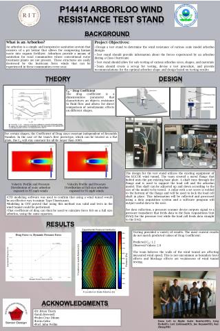
Problem Statement The primary objective of this project is to design a scale model and a full-size test stand that will help determine the wind resistance of various arborloo designs. The scale model test stand should replicate the forces experienced by a Class I hurricane, and the results should be easily comparable to the lower speed, full-size results. • Measure wind speed, forces of aerodynamic effects • Create test procedure for full size and scale testing • Recommendations for future design of arborloos
Detailed Design Review Objectives From this review, the team hopes to: • Present final design for small scale testing and receive feedback • Present draft design for full scale testing and model • Solicit ideas for implementation for full scale testing • Get recommendations from arborloo base teams on future possible arborloo design configurations • Receive input on test plans / procedure
Scaling Laws • Dimensional Analysis – allows for identification of key parameters • Reynolds Number allows to determine model test velocity given a full size expected velocity • Drag Coefficient allows us to find the expected full size drag force given the model measured drag force
Revisiting CFD Analysis Pressure Distribution mainly constant with fast drop offs at edges Aid in placement of pressure reading points
Revisiting CFD Analysis CFD Results showed a CD of approximately 1. Will assume a conservative 1.5. Dynamic Pressure at 95 mph wind expected to be ~1 kPa. Dynamic Pressure at 20 mph wind expected to be ~ 50Pa
CH7 Moderate Speed Flow Video Fox & McDonald
CH7 High Speed Flow Video Fox & McDonald
Tackling the Problem • Use a load cell to directly find the drag force on the arborloo • Load cell assembly also used as attachment point for arborloo • Use pressure sensors to verify CFD results • Pressure sensors methodology will allow for comparison to full scale testing
Scaled Test Stand Design Overview • This design contains: • Plywood Base • Load Cell Assembly • Pressure Sensor • Pressure Multi-sensor • Looking for feedback on: • Assembly package quality • Full scale testing • Testing equipment choices & improvements
Scaled Test Stand Design Specs Addressed : S7 • RIT Wind Tunnel • Test Model will need to be about 1.2 ft tall max (1/6th scale)
Test Arborloo Specs Addressed : S3,S4,S13,S14 • Plywood Model • 6” x 6” x 12” • Uses pressure sensors and load cell to ensure accuracy of data
Load Cell Specifications Mechanical Load Ratings: • Fx,Fy= 120 N • Fz=240 N • Mx,My = 6.0N·m • Mz=6.0 N·m Specs Addressed : S3
Expected Loads FD= ½ρV2AcD = 0.5*(1.225 kg/m^3)*(42.4688m/s)2 *(0.3048m*0.1524m)(1.5) – Conservative = 77.0 N = 17lbf ✔ M = FD*L = (77N)*(0.1524m) – Half the height of the arborloo = 11.7 N·m ✗ Adjustable Height Load Cell Assembly allows adjusting moment arm Specs Addressed : S3
Pressure Multi-sensor • Sensor relay provided by Prof. Wellin • Functions as a giant valve, opening and closing inputs to one pressure output • Hooked up to an Omega PX277-30D5V Pressure Transducer • Pressure transducer outputs to DAQ that feeds into the computer Specs Addressed : S3
Pressure Sensor • Pressure sensors will give general pressure distribution • Surface area of arborloo face is known • 1/6 scale: Area=18 in^2 = 0.0116 m^2 • Expected Dynamic Pressure: Q= ½ ρV2= 0.5*(1.225kg/m^3)*(42.4688m/s)2= 1.104 kPa • Pressure Rating: 10 psi differential ~70 kPa✓ • Average Pressure x Area = Distributed Force
Pressure Transducer • Expected Dynamic Pressure: 0.5*(1.225kg/m^3)*(42.4688m/s)2 = 1.104 kPa • Omega PX277-30D5V • Pressure overload 10psi = 68.95 kPa • 1.104 kPa << 68.95 kPa
Anemometer • Mounted in wind tunnel behind test stand • Cost: ~$200each • Used to verify windspeed at arborloo • Can also measure temperature Specs Addressed : S1,S15
Data Acquisition Device • DAQ Device: NI: USB-6008 • Multifunction Data Acquisition • Compatible with pressure sensors • No added cost to design • Made to be used with LabView Specs Addressed : S1,S2,S3, S15
Matlab Codes for Data Analysis Script inputs: Pressure Force Code outputs: Drag Force, Coefficient of Drag, Stress Specs Addressed : S1,S2,S15
Preliminary Test Procedure Instructions: 1. Release pneumatic hold by turning the pressure knob counter-clockwise to the left position. 2. Lower the pistons by holding onto the red button. 3. Insert and align plywood base into wind tunnel test section. Handle plywood with care. 4. Raise the pistons by holding onto the green button. 5. Lock the pneumatic pistons by turning the pressure knob clockwise to the right position. 6. Attach load cell assembly to plywood base through the bottom. Fasten securely. 7. Attach load cell assembly to the “shelf” inserted close to the center of arborloo design. See “Future MSDII Document on Guidelines for creating an attachable arborloo”. 8. Attach barbs to face of arborloo facing the wind. Use specified barb size only. See “Future MSDII Document on Guidelines for placing Pressure Sensors”. 9. Attach and secure anemometer inside the wind tunnel away from the test arborloo. 10. Use Thermometer to measure room temperature. Room temperature must be between 60°F and 80 °F. 11. Load software and calibrate all sensors. See “Future MSDII Document on Guidelines for calibrating sensors”. 12. Close plexiglass walls and secure control surface. 13. Turn on Wind tunnel. Push start button and use arrows to increase or decrease wind speed. Read anemometer so that the desired wind speed is achieved. Wait 2-3 minutes for steady conditions to apply. 14. Start collecting data. 15. Let test run, recommended time for test duration is 5 minutes. Note: Do not run wind tunnel for longer than 20 minutes as this may cause overheating. 16. Stop collecting data. 17. Turn off Wind tunnel. Push stop button. 18. Repeat for different arborloo model.
Limitations of Design • Inability to compare small scale results to large scale result for non-sharp edged objects i.e. cylindrical arborloos. • Windtunnel max speeds of approximately only 120 mph.
Design Overview - Full Scale • Design Includes • Large Scale Arborloo Sarah will provide • Self standing – sand bags • Utilize Pressure Sensors methodology • Netting environment for protection • Locking mechanism for equipment • Dynamic Pressure at 20 mph wind expected to be ~ 50Pa • Drag Force ~ 123 N
Possible Testing Locations Ramp BLDG 7A-7B Soccer / Track Field SAU Turf Field Meadow / Hill
BOM / Specs Addressed : S8, S9
BOM / Specs Addressed : S8, S9
Moving forward Over Break: • Order necessary parts • Have machine shop make necessary parts MSD II-Week 1-3 • Test Small Scale Model in Wind Tunnel • Analyze Data • Begin Full Scale model creation
Summary • Introduction • Engineering Requirements • Detailed Design Review Objectives • Revisiting CFD Analysis • System Architecture • Scaled Test Stand Design • Fullscale Test Stand Design • Test Plans/Procedures • Risk Analysis • Project Plan • Moving Forward