EE 166 Design Project
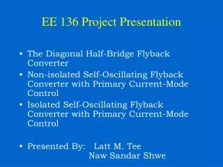
EE 166 Design Project. 4 – Bit Magnitude Comparator. Design By Man Hong Liu Kee-Hoon Choi Tak Chuen Wong. Diagram of 4-Bit Comparator. A3. A2. A1. A0. B3. B2. B1. B0. 4 – Bit Magnitude Comparator. GT. EQ. LT. Specification. Power : Less than 0.25 W Frequency : 200 MHz

EE 166 Design Project
E N D
Presentation Transcript
EE 166 Design Project 4 – Bit Magnitude Comparator Design By Man Hong Liu Kee-Hoon Choi Tak Chuen Wong
Diagram of 4-Bit Comparator A3 A2 A1 A0 B3 B2 B1 B0 4 – Bit Magnitude Comparator GT EQ LT
Specification Power : Less than 0.25 W Frequency : 200 MHz AMI06 Technology
Method • Used Velilog to verify our logic • Hand Calculation to determine approx. delay time and speed. • Completed all the logic gate: AND, XNOR, NAND, Inverter (transistor size, simulation) • Integrated all parts (Modification if needed) • Layout (Modification if needed) • Extracted Simulation
Sub – Systems of our Design • Three Sub-Systems a. Equal Module (A = B) b. Less than Module (A < B) c. Greater than Module (A > B)
Equal Module Output high when two inputs equal (A = B) Four 2-input XNOR Gate One 4-input NAND Gate
Less Than Module Output high when input A is less than input B. (A < B) Three Inverters Five 2-input NAND Gates One 3-input NAND Gate Two 4-input NAND Gates Three signal from EQ module (EQ3, EQ2, EQ1)
Greater Than Module Output high when input A is greater than input B. (A > B) Three Inverters Five 2-input NAND Gates One 3-input NAND Gate Two 4-input NAND Gates Three signal from EQ module (EQ3, EQ2, EQ1)
Transient Response A3 < B3 A = B A3 > B3
Results Power : Approx. 0.26 mW (within 5 %) Time Delay : 830 ps for EQ module Good !!! We met our specification
Results Power : Approx. 0.20 mW (within 5 %) Time Delay : EQ Module = 810 ps (LT & GT are faster than EQ) Good !!! We met our specification
Conclusion Problem : Too much Power consumption. Solution : We simplified our logic. We deleted some of inverters. Result : Power goes down.
Conclusion Better result from layout than schematic After all, our design works !!!