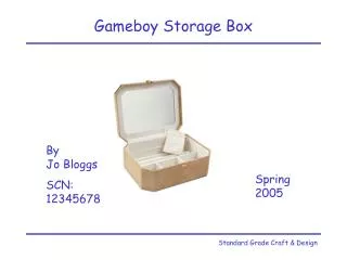
Gameboy to Intel x86 Static Binary Translator
Gameboy to Intel x86 Static Binary Translator. Jim Clark David Galos. The Nintendo Gameboy. CPU – 8 bit Sharp LR35902 running at 4.19 MHz, custom for Gameboy but similar to Intel 8080 and Zilog Z80 8kB VRAM and 8kB working RAM Game code stored on changeable cartridges.

Gameboy to Intel x86 Static Binary Translator
E N D
Presentation Transcript
Gameboy to Intel x86 Static Binary Translator Jim Clark David Galos
The Nintendo Gameboy • CPU – 8 bit Sharp LR35902 running at 4.19 MHz, custom for Gameboy but similar to Intel 8080 and Zilog Z80 • 8kB VRAM and 8kB working RAM • Game code stored on changeable cartridges
To run this program on a different architecture……… • Emulation • Each CPU opcode translated into a function which affects the “registers” in the same way • CPU registers emulated using data structure in high level language • Entire area of mapable memory stored in data structure in high level language • Binary Translation • Each CPU opcode translated from its original architecture to the targets equivalent • CPU registers mapped directly from source to target • Entire area of mapable memory stored in targets
An emulation approach……. • Map each register into a variable in the high level language
Our binary translation approach….. • Map each register from the source architecture into an equivalent in the target
An emulation approach……. • Access memory through functions
Our binary translation approach….. • Setup the .data section in an x86 asm file • Address through labels
An emulation approach……. • Translate each opcode into a function
Our binary translation approach….. • Translate each opcode to its equivalent on the target architecture ADD A,E becomes addb %cl, %ah CP A,B becomes cmpb %bh, %ah NOP becomes nop
Emulation within binary translation • Need to account for peripherals • The generated .asm file assembled, then linked with a high-level C program • Call the “fake_stuff” after each instruction, then return • Nesecary to emulate the effects of the LCD controller, button input, DMA etc.
How our translator works • A program, written in C, generates an x86 asm file from the given Gameboy ROM file • Object files are generated from this .asm file and the C program containing the “fake stuff” • These files are linked, resulting in the output of a single Windows .exe file
Generating an x86 asm file • Input is a Gameboy ROM file, a 32K binary • As this input file is simply a binary there is no way to distinguish code from data • This was our first hurdle in the project
Code or Data? • Consider the following 3 bytes arbitrarily pulled from Tetris: • This could be: • A 1 byte instruction followed by 2 bytes of data • A 2 bye instruction followed by 1 byte of data • A 3 byte instruction • 1 byte of data, a 1 byte instruction, and another byte of data……………
If the series of data is interpreted as a 3 byte instruction, 21 corresponds to the instruction LD HL,d16 which loads immediate 16 bit data into register HL. Thus this instruction would load the value 0xB0E8 into register HL • Another way this could be interpreted is if 21 were a byte of data followed by the 2 byte instruction E8 B0. This is also a valid opcode, and translates into ADD SP,r8.
Further complicating things, this sequence could be interpreted as 2 bytes of data, 21 and E8, followed by the single byte instruction B0. B0 is a valid opcode as well, and translates into OR B. • Finally, this may not even be code! It could simply be 3 bytes of data. As you can see, it is very difficult to distinguish code from data as they are intermixed throughout the ROM.
How we solve this problem • When generating the .data section, treat each byte in the entire file as if it is data .global _data0574 _data0574: .byte 0x21 .global _data0575 _data0574: .byte 0xe8 .global _data0576 _data0574: .byte 0xb0
How we solve the problem • When generating the .code section, assume each byte is a complete instruction, but DON’T skip over the extra bytes we pulled in! .global _code0574 _code0574: movb $0xb0e8,%dx _code0575: addl $0x8838, %esi andl $0x0000ffff, %esi _code0576: orb %bh, %ah
Why this works • If we are writing to an address, we know it’s data, so we append an offset to _data0000 • If we are jumping to an address, we know it’s code, so we append an offset to _code0000