Download
1 / 5
60 likes | 119 Vues
Learn about the components of the rubidium apparatus, how it works, and ongoing developments. The rubidium spin filter is a versatile tool for studying electron polarization and spin structure.

E N D
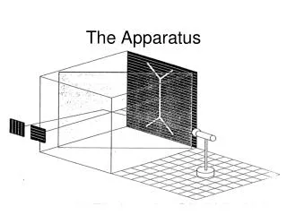
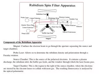
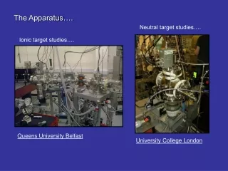
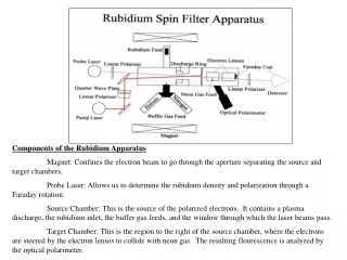
Components of the Rubidium Apparatus Magnet: Confines the electron beam to go through the aperture separating the source and target chambers. Probe Laser: Allows us to determine the rubidium density and polarization through a Faraday rotation. Source Chamber: This is the source of the polarized electrons. It contains a plasma discharge, the rubidium inlet, the buffer gas feeds, and the window through which the laser beams pass. Target Chamber: This is the region to the right of the source chamber, where the electrons are steered by the electron lenses to collide with neon gas. The resulting flourescence is analyzed by the optical polarimeter.
Introduction The polarization of a beam of electrons is given by where I () is the number of electrons with spin “up” and I () is the number of electrons with spin “down” along a given axis. Polarized electrons are an important probe of spin structure, and can be used to study elementary particle interactions, magnetism at surfaces, experiments in chirality (or handedness) of matter, and more1. Present state-of-the-art sources of polarized electrons are based on the photoemission from gallium arsenide crystals and the chemi-ionization of metastable He. Both, under ideal conditions, can yield ~100 μA with 70% electron polarization1. However, these sources are complicated and difficult to use. Our rubidium spin filter requires modest equipment and is relatively easy to use2 .
How it Works The source chamber is where all of the action occurs. Rubidium vapor is admitted through a side arm and the entire source chamber is heated to vary the density of rubidium vapor. A circularly polarized laser, tuned to the rubidium resonance, optically pumps the rubidium3. We use a probe laser to determine the density and polarization of the rubidium vapor. • * The buffer gas has several important roles to play. • Polarized rubidium can become depolarized in several ways. When the laser excites the atom to the 5 2P1/2, ms = +1/2 state, the atom can decay down to either ground state. If the radiation from this transition hits a polarized atom, the atom is depolarized. This process is known as radiation trapping. Radiation trapping can be prevented by quenching the excited state with nitrogen (dotted blue line in above graph), transferring the energy to molecular vibrations of N2. • The buffer gas also helps prevent depolarization by limiting the diffusion to the walls. Once a polarized atom strikes the wall it becomes depolarized. • The buffer gas pressure broadens the rubidium absorption line, allowing more of the laser light to be used. • The discharge from the gas provides the free electrons from which the current is derived. • The gas pressure sets the electron beam current and polarization (graph on left). Meanwhile, the buffer gas*, typically nitrogen, generates the electrons through a discharge between the anode and cathode rings. The electrons acquire some of the rubidium polarization through spin exchange as they travel within the discharge. The degree of electron polarization depends on the electron energy and the buffer gas pressure. High pressures produce high rubidium polarizations and good spin exchange. Unfortunately, as shown in the graph below, such pressures also decrease the electron beam current.
Rb Polarization Vs. Nitrogen Pressure Electron polarization Vs. Laser Power with Helium Electron Polarization and Rb Polarization Vs. Laser Power with Nitrogen Results Overcoming the inverse relation between the pressure of the gas in the source chamber and the electron beam current is a challenging problem. In our first experiments, nitrogen was used as the buffer gas and produced about 2 A with 18% electron polarization. Helium seems to do better, yielding 4 A with nearly 23% electron polarization. We are considering other gases as well. The Ramsauer minimum in the electron scattering cross-section from the heavy noble gases allows them to assist the optical pumping without affecting the electron beam current much.4 Therefore mixes of argon and nitrogen may give even better results. Initial testing with argon have been promising but not conclusive.
Recent and Future Developments... • The electron polarization can never be greater than that of the rubidium. So, optically pumping the rubidium is the key to making this apparatus work Our first results, published in October of 1998 2, were obtained with a 200mW dye laser. Since then we have substituted a 10W laser diode array, which greatly simplifies the laser tuning. Other developments • Various mixtures of buffer gas, such as nitrogen-helium and nitrogen-argon, are under investigation. They will help polarize the rubidium without great adverse effects on the electron current. • The plasma discharge inside the source chamber may be affecting the rubidium density and polarization in undesirable ways. We are studying this problem as well. • An even newer diode laser array has been purchased to enable us to narrow the frequency width of the laser. This allows more power to be delivered near the resonance of the rubidium. This method utilizes a holographic grating to feed the 1st order reflection back into the laser. This external cavity feedback reduces the spectral linewidth by an order of magnitude. The 0th order reflection is guided into the source chamber for optical pumping. Below is a diagram of this procedure.5