Download
1 / 16
191 likes | 475 Vues
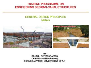
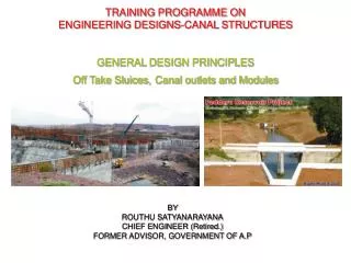
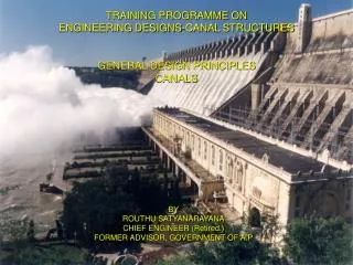
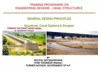
TRAINING PROGRAMME ON ENGINEERING DESIGNS-CANAL STRUCTURES GENERAL DESIGN PRINCIPLES Canal Falls or Drops. BY ROUTHU SATYANARAYANA CHIEF ENGINEER (Retired.) FORMER ADVISOR, GOVERNMENT OF A.P. THANK YOU. Canal Falls or Drops. Introduction: Canal fall or drop:

E N D
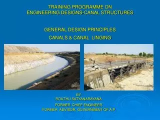
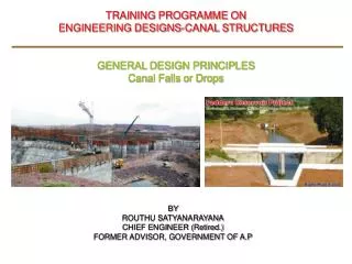
TRAINING PROGRAMME ON ENGINEERING DESIGNS-CANAL STRUCTURES GENERAL DESIGN PRINCIPLES Canal Falls or Drops BY ROUTHU SATYANARAYANACHIEF ENGINEER (Retired.)FORMER ADVISOR, GOVERNMENT OF A.P
Canal Falls or Drops • Introduction: • Canal fall or drop: • A structure designed to secure lowering of the water surface in a canal and to dissipate safely the surplus energy so liberated, which otherwise scour the bed and banks of the canal Necessity: • Velocity in a canal is a function of the slope of the canal. There is a limit for the velocity, so that the canal bed can neither be scoured nor silted up. Hence there is a limiting surface slope in the canal. • The slope of the country, where the canal system has to run will naturally be steeper than the surface slope the canal system that has to come up. To bring the velocity with in the permissible velocities, falls or drops are introduced at suitable locations. • Falls are combined with regulators, bridges, and escapes. • Classification or Type of Falls/Drops: 1. Vertical drops. 2. Glacis falls • Straight Glacis with baffle (Inglis fall) • Straight Glacis without baffle
Canal Falls or Drops 3. Trapezoidal Notch falls 4. Well type, Cylinder Falls or Well Syphons. 5. Ogee falls (with and without raised crest) 6. Stepped falls 7. Meter and non-meter falls • Required Basic Data: • Site plan with contours showing the flow direction. • Hydraulic particulars of the canal both upstream and downstream • Cross sections of the canal with levels, such as BL, FSL, TBL, GL, marked on the CS. • TPs Particulars, taken up to hard strata or to a minimum depth of 2m below CBL or ground level which ever deeper with soil classification. • Bearing capacity of the foundation strata.
Canal Falls or Drops • Hydraulic design: • Fixation of crest: • Throat width of drop wall, • Linear water way • Design of Stilling Basin: • Invert level of the cistern • Length of the basin • Level of end sill • And other components. • Design of drop wall. • Transition lengths on upstream and downstream. • Check for Scour depth • Check for exit gradient • Check for apron thickness due to uplift. • Structural Design: • Design of body wall • Design of stilling basin • Design of wings, returns.
Canal Falls or Drops • Trapezoidal Notch Fall: • It consists of number of trapezoidal notches constructed in a high crest wall across the channel with a smooth entrance and a flat circular lip projected down stream from each notch to spread out the falling jet. • The notches could be designed to maintain the normal water depths in u/s at any two discharges, as the variation at intermediate value is small. • There would neither be drawdown nor heading up of water, as the channel approaches the fall. These falls are Simpler, economical and popular. • Design – Trapezoidal Notch: • The crest level of the fall normally is u/s bed level, • The total linear water way should not be more than the bed width of the canal on the d/s side. • The discharge for one notch is computed and the number of notches designed by trial and error method considering full supply discharge and half supply discharge...
Canal Falls or Drops Discharge formula: Q = 2.25 [L + 0.4nH] H3/2 Where Q = discharge per notch in cumecs n = a constant L= Bottom width of notch H = Depth of water. Top width of notch =L+ n.H and the thickness of pier notch >0.5H
Canal Falls or Drops • Glacis fall: Straight Glacis fall: • It is a modern fall, a Straight glacis generally with a slope 2:1 is provided after a raised crest. • The hydraulic jump occurs on the glacis causing sufficient hydraulic jump. • Suitable up to 60 cumecs and 1.5m drop. Baffle falls or Inglis falls: (used for flumed) • For all discharges and for the drops more than 1.5m. • These drops are flumed. • These drops can be meters. Design principles: • The following are main components: 1. Up stream approach 2. Clear width of the Throat (Bt), normally down stream bed width. 3. Down stream glacis 4. Down stream expansion 5. Down stream Energy Dissipation.
Canal Falls or Drops • Energy Dissipation : • It is the portion of the fall on the d/s side of the crest, where the surplus energy is being destroyed. It consists of: • Sloping glacis (if any). • The cistern • Roughness devices and the deflectors to deflect the high velocities. • Cistern: • The object is three fold: • To reduce the intensity of impact of the dropping jet against the d/s floor. • Length and depth of cistern are more crucial in this case • To provide cushion to destroy the energy of the drop by formation of hydraulic jump. • In a sloping glacis a reverse curve at the lower end to turn the hypercritical jet to horizontal to a horizontal before it impinges against the sub critical flow of the lower channel, thus creating an hydraulic jump. • Thus the invert level of the cistern be kept at 1.25 times below the d/s energy line(Ef2) or a minimum 300mm below d/s bed level. • The length of cistern be 5Ef2 to 6Ef2 • To produce reverse flow by providing suitable end wall to ensure an impact in the cistern
Canal Falls or Drops • In case the hydraulic jump occurs on the glacis the energy dissipation will be incomplete and additional roughening devices such as friction blocks, end sill, deflectors etc., • Cistern without impact: • In this case hydraulic jump does not form, in case high drowning ratio and low falls.
Canal Falls or Drops • Glacis fall: • Minimum fluming ratio: Drop height Fluming ratio 1. Up to 1m 66% 2. 1m to 3m 75% 3. Above 3m 85% 4. Maximum Bed width (d/s bed) • Coefficient of discharge: Discharge over the crest Q = C Bt D3/2 Where C= Coefficient of discharge Discharge in Cumecs Value of C 0.06 to 0.30 1.66 0.31 to 1.50 1.67 1.51 to 15.00 1.68 Over 15 1.70 D = Head over the crest. Crest level = u/s TEL- D Crest level should not > 0.4 d ( where d=u/s FSD) Length of crest = 2/3 x D
Canal Falls or Drops • When there are piers Bt will be reduced as (Bt - 0.2nH), where n= No. of piers. • Crest length = 2/3 D and for vertical falls it should be 0.55 D1/2, a minimum 0.5m. • Down stream Glacis: 1. D/S slope 2:1 can be increased to 1:1 2. If baffle platform is introduced the slope can further be increased to 2/3:1 • Baffle Platform: • It is a low weir constructed at the end of cistern, working on the principle of horizontal impact for energy dissipation. • The jump is held stable on a horizontal platform by means of baffle wall. • To head up water to upstream to form hydraulic jump. • To with stand the impact of the high velocity jet to dissipate the energy. • Fixing Sill Level: • Sill level of the platform = Down stream FSL-d’x Where d’x = Hx+ dx- HL dx = 0.985d0.52.Hx HL= K0.52. Hx HL = Actual height of drop K = Bed width of canal on d/s/ Over all width of wall
Canal Falls or Drops • Baffle wall: • Height of Baffle wall (hb) = dc-d2 Where dc = (q2/g)1/3 and d2 = 0.183.(q) 0.89 (Hx) -0.35 q = discharge per meter width. Thickness of baffle wall = 2/3 hb Length of Baffle plat form = 5.25 hb • Cistern: • The platform below the baffle wall up to the deflector wall is known as the cistern. • Depth of cistern = 0.1 times down stream FSD and should not <300mm/150mm • Cistern length 5 dx The baffle plot form should join the toe of glacis with a radius D and to the baffle wall with radius R = 2/3 hb • Deflector wall: Deflector walls of height one tenth of d/s FSD provided at the down stream end of the cistern.
Canal Falls or Drops • Well Type or Syphon Well drops: • It consists of well with pipe or an RCC box at its bottom, carrying water from inlet well to a downstream well or a Cistern. • Down stream well is necessary if the discharge is greater than 0.29 cumecs and the fall is > 1.8m • The water falls in to the inlet well through a trapezoidal notch constructed in the steining of the well. • Simple vertical Drop: • It is a simple fall broad crested weir with high raised sill, The nappe impinges into the water cushion below • There is no hydraulic jump and the energy dissipation is brought about by the turbulent diffusion, as the high velocity jet enters the deep pool of water down stream. • The discharge is computed using the formula: Q in cumecs = 1.66L.d3/2 Where L is the bed width on d/s side and dis depth of water above crest in m.