TRAINING PROGRAMME ON ENGINEERING DESIGNS-CANAL STRUCTURES GENERAL DESIGN PRINCIPLES
640 likes | 807 Vues
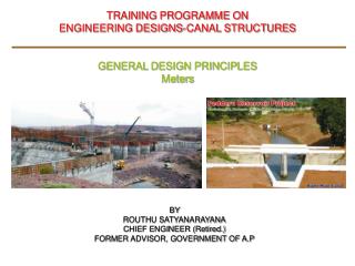
TRAINING PROGRAMME ON ENGINEERING DESIGNS-CANAL STRUCTURES GENERAL DESIGN PRINCIPLES Off Take Sluices, Canal outlets and Modules. BY ROUTHU SATYANARAYANA CHIEF ENGINEER (Retired.) FORMER ADVISOR, GOVERNMENT OF A.P. Off Take Sluices And Modular Outlets. Definition: Off –take sluices:

TRAINING PROGRAMME ON ENGINEERING DESIGNS-CANAL STRUCTURES GENERAL DESIGN PRINCIPLES
E N D
Presentation Transcript
TRAINING PROGRAMME ON ENGINEERING DESIGNS-CANAL STRUCTURES GENERAL DESIGN PRINCIPLES Off Take Sluices,Canal outlets and Modules BY ROUTHU SATYANARAYANACHIEF ENGINEER (Retired.)FORMER ADVISOR, GOVERNMENT OF A.P
Off Take Sluices And Modular Outlets • Definition: • Off –take sluices: • It is a small structure which admits water from the parent canal to a distributing channel or to a water course or a filed channel. • Water distribution system is classified as: • 1. Supply System or Conveyance System: • Discharge >5.66 cumecs(200 c/s) and perennial and always gated. • 2. Distributory System: Discharge < 5.66 cumecs (200 c/s), runs on and off system, No gates, Water will be distributed proportionately through Modules (APM or OFM). • Gated off takes: • i. Square opening or ii. Rectangular openings or iii. Hume pipes • Sill levels will be kept at bed level or above bed level of parent canal depending on the % discharge of the OT with Parent canal discharge:
Off Take Sluices And Modular Outlets • Sill levels will be kept at bed level or above bed level of parent canal depending on the % discharge of the OT with Parent canal (PC) discharge: _____________________________________________________________________________ % discharge Height of sill of OT above CBL of PC when FSD in PC in m ------------------------------------------------------------------------------- 2.14 2.14 to 1.22 below 1.22 ____________________________________________________________________ >> 15% 0.075 … … 10% to 15% 0.15 0.075 … 5% to 10% 0.30 0.15 0.075 2% to 5% 0.30 0.30 0.15 <2% 0.30 0.30 0.30 _____________________________________________________________________ • Minimum size of Hume Pipe: : 300mm • Main and branch canals : 900mm • Distributory : 230mm for Q=14.15 to 2.83 cumecs and 150 mm for Q < 2.83 cumecs • The level difference between sill level & CBL of parent canal negotiated by slope
Off Take Sluices And Modular Outlets • Driving Head: • The driving head at off take is arrived considering Half Supply discharge in parent canal, when the distributory canal runs at full supply level • Driving Head=Half supply discharge level in parent canal-FSL in distributory Type of Canal Driving head in mm Channels taking off from main & branch canals 150 Channels taking off from distributaries 75
Off Take Sluices And Modular Outlets • Driving Head: • The working heads to be usually allowed (as per Para 2.80 of CBIP Publication No. 171. Manual on Irrigation and Power channels by CWC) Channel Minimum working head Head over field 75mm Major distributaries to minor 300mm At outlet 150mm Branch to branch or major distributaries' 500mm From main canal 600mm Slope of water course 1 in 5000
Off Take Sluices And Modular Outlets • Vent way: • Vent way calculated from the formula: Q the discharge in cumecs = C.A.(2gH)1/2 where C = a constant : 0.62 for Square or Rectangular opening 0.75 for circular opening A = Area in Sq. m H = Driving head in m Q for Rectangular a Square opening = 2.745 A (H)1/2 Q for Circular opening = 3.322 A (H)1/2
Off Take Sluices And Modular Outle • Check for driving: • Length of barrel worked out with respect to position of D/S head wall. The flow condition in the barrel is dependent on D/S condition in the O.T. channel immediately below the vent way. TELs at entrance and exit of barrel are calculated and checked for assumed level. • Transitions: The U/S and D/S transitions are provided with 1 in 3 and 1 in 5 splay respectively as per practice. • Stilling Basin: • The type of stilling basin to be provided depends upon the velocity at the entry of barrel. If the entry velocity is above 6.1 m/sec. (20 ft/sec) the barrel floor is depressed both for rectangular and square vents based on the hydraulic jump calculations. In case of normal velocities which are of the order of 4 m/ sec the floor is at the same level and the floor is checked for arch action for the uplift pressure. • The design of hydraulic jump basin for energy dissipating arrangements can be followed from ‘Small Dams’ by U.S.B.R. or as per I.S. 4997 – 1968. For shooting flows, an impact type basin - VI with R.C.C. baffle wall is to be provided. The baffle wall is to be designed for the maximum water thrust with 50% impact factor when full discharge is let out in the canal.
Off Take Sluices And Modular Outle • Off – takes with hume pipes: Minimum diameter for off takes from main/ branch canal and distributaries is as follows: Main/ Branch canal Distributory Minimum Diameter 0.90m i) 14.15 to 2.83 cumec discharges – 0.23m φ ii)2.83 cumec and less – 0.15m φ • Laying of O.T. Pipes: The condition of laying of off – take pipes such as “Negative projecting condition”, and “Trench condition” etc., relevant to the individual cases are followed as per IS. 783 – 1985 for laying and jointing. For the selection of proper size of pipe for the vents, IS. 458 is to be followed
Off Take Sluices And Modular Outle • Controlling arrangements Type of control to be adopted: (i) For pipe sluices of 150 mm dia. and below and vents of equivalent area with F.S.D of parent canal not exceeding No control 1.22 m. and O.T discharge 0.045 cumecs (1.5 c/s )and less (ii) For pipe sluices of diameters above 150mmand up to and including 300 mm with F.S.D of parent canal not Stem shutter exceeding 1.22 m. For all sluices where the FSD in the parent canal Screw is more than1.22 m and for sluices of larger vent ways. gearing shutter
Canal Outlets And Modular Outlets • Canal Outlets and Modular Outlets: • Definition: • Canal outlet is a device through which water is released from a distributing channel into a water course whose discharge is less than 0.085 cumecs • Classification of Outlets: • Non modular out lets • Semi modular out lets • Modular out lets
Canal Out lets & Modular Outlets • Requirement: • Structurally strong, • With out any moving parts, • Difficult for the cultivators to interfere and if so easily detectable, • Work efficiently for small working heads, • Can draw fair share of silt and economical.
Canal Out lets & Modular Outlets • Non-Modular outlets: • It is a pipe outlet with one end submerged in water course fixed horizontally at right angle to the flow.. • Consists of circular or rectangular opening and pavements. • Discharge widely varies with the change of water level either in the canal or the water course. • Discharge Q in cumecs = CA(2gH)1/2 (Q=5 or6 A H1/2 for pipe sluices in FPS) Where, A= cross sectional area of the pipe in sq. m. C= Coefficient = 1__ [d/f(L+1.5d/400f)]1/2 2 x 10⁵ H= difference in water levels, f = coefficient of fluid friction, 0.005 and 0.01 for clear and encrusted iron pipes and 0.0075 for earthenware pipes. L = length of pipe in m d = diameter of the pipe in cm • Drowned pipe outlet and Masonry sluice comes under this category.
Canal Outlets & Modular Outlets • Semi-Modular outlets: • Non-Modular outlet works as Semi-Modular outlet if the exit end of the pipe is made to discharge with a free fall. In this case working head H is the difference between water level in the parent channel and the centre of pipe(PSM) • It is independent of water level in water course up to minimum working head. • Discharge increases with increase in the water levels in the distributaries'. • Pipe outlets, venturi flumes, open flumes and orifice semi modules are the examples. • Semi-Modular outlets or Flexible modules • Open Flume Outlet (OFMs) • Crump’s Adjustable proportionate Module (Crump’s APM) • Adjustable Orifice Semi module (AOSM) • Pipe Semi Module
Cross Masonry Works- Modular Outlets • Semi-Modular outlets or Flexible modules • Open Flume Outlet (OFMs) • Crump’s Adjustable proportionate Module (Crump’s APM) • Adjustable Orifice Semi module (AOSM) • Pipe Semi Module
Canal Outlets & Modular Outlets • Open Flume Module(OFM): • A smooth weir with a throat constricted sufficiently to ensure velocity above critical, and long enough to ensure that the controlling section remain with in the parallel throat at all discharges up to the maximum. • A gradually expanded flume is provided at the outfall to recover the head. • The entire work can be built in brick, but the controlling section is provided with cast iron or steel bed and check plates. • Throat width Bt never kept less than 6cm hence it is necessary to raise the crest level of the out let much above bed level. • Working head required with a 1 in 5 glacis and side walls splaying at 1 in 5 is 20% of depth of water above the crest of out let. • Formation of hydraulic jump makes the out let independent of water level in the out let channel
Canal Out lets & Modular Outlets • Open Flume Module (OFM): • Q in Cumecs = K Bt H3/2 Where K = a constant depending upon the width of the flume Bt = throat width of the weir (minimum 6 cm) For Bt , 6 cm to 9 cm K=1.6 9 cm to 12 cm K= 1.64 > 12cm K= 1.66 H = head over crest in m. • It is most suited to tail cluster and proportionate distribution. • Length of throat (crest) = 2H • Setting H = 0.9 D, where D is FS dept of Parent canal • Minimum modular working head = 0.2 H • Crest level = U/S FSL – 0.9 D • U/S approach to throat ----- one curved and diverging and another straight • D/S expansion------- splayed to 1 in 10 to meet the bed width of the out let channel
Canal outlets & Modules • Adjustable Orifice Semi Module (A.O.S.M) or Adjustable Proportional Module (APM) • Discharge through outlet in cumecs Q = 4.03 Bt Y Hs1/2 Y =Height of opening in meters. Bt =Throat width (minimum 0.06 m ) H =Depth of water in parent canal over the crest in meters Hs = Depth to under side of the roof block below FSL of parent canal. Hs = H – Y , Hs ≤ 0.80 D y > (2/3 ) H Setting of crest, H = 0.750 x D , where D = Full supply depth in the parent canal Setting of crest shall not be below D/S B.L.
Canal outlets & Modules Setting of crest shall not be below D/S B.L. Minimum modular head Hm = 0.75 Hs for modularity between full supply and any fraction of full supply. Crest level ≈ U/S FSL- 0.75 D Length of throat = width of roof block + H U/S slope of glacis = curve with radius 2H. U/s approach wings =one curved and the other straight, top at FSL + 0.15 m D/S expansion =1 in 10 to meet bed width of outlet channel
Modular Outlets • Crump’s Adjustable Proportionate Module or adjustable Orifice Semi-Modules ( APM): • Most commonly used module. • CI base, CI roof block and check plates on sides nucleus around masonry. • It can not be tampered and can conveniently adjusted at a very small cost. Setting of d/s wing wall of approach, W = k(q/Q){Bu+D/2} Where, k= ratio between mean velocities of distributory and the water course q= discharge in cumecs of the water course Q= discharge in cumecs in the distributory Bu= bed width of the distributor u/s of outlet D= depth of water in the distributory Q in cumecs k 0.283 1.00 0.283 to 1.415 1.25 1.415 to 5.660 1.50 > 5.660 2.00
Canal Out lets & Modular Outlets • Adjustable orifice Semi Module (AOSM) • An orifice provided with gradually expanding flume on the d/s side of the orifice. The flow through the orifice is super critical , resulting in the formation of hydraulic jump in the expanded flume portion. The formation of jump makes the discharge is dependent of water level in the out let channel.
Canal Outlets & Modules • Pipe semi module • Design criteria The discharge through pipe semi module is given by Q = Cd . A (2g hc )1/2 Where Cd = 0.62 for free pipe out let hc = head on U/S above the centre of pipe hc should be more than 1.5 times the dia of the pipe proposed. The above formulae can be reduced to Q = 0.62 x √ (2x 9.81 ) A √ (hcnt) =2.746 A hc1/2 • For free fall condition set the F.S.L of OT Channel below the pipe sill level keeping in view the command under the pipe sluice .It is a simplest type and the users will appreciate.
Modular Outlets • The suitability of the type of the semi module outlet is determined based on the ratio of parent canal discharge (Q) to the discharge of the out let (q) and the throat width (Bt) as detailed below. i) for (Q/q ) < or = 20 and B t ≥ 6 cm Open Flume Module( OFM) ii) for (Q/q ) < or = 20 and B t < 6 cm Adjustable Proportional module ( APM ) for (Q/q ) > 20 • If the above requirements do not suit the site condition, provide pipe semi module (where possible) with diaphragm of required diameter inserted at the first joint. The minimum diametre of pipe used will be 150 mm. • The above conditions are further explained as below • Arrive at the ratio of parent channel / out let channel. • If it is < or = 20, select OFM. Calculate the Bt ( throat width ), using weir formula. If Bt is > 6 cm it is ok. Otherwise select A.P.M. • Work out the Bt using the sluice formula setting the crest of outlet at less than 0.80 D from FSL of Parent Channel and adjusting the height of outlet opening. If Bt = or > 6 it is ok • Otherwise go for pipe semi module (PSM), if it is possible to do so. • Check for proportionally
Modular Outlets DESIGN - EXAMPLES HYDRAULIC DESIGN OFM – APM - PSM
Cross Masonry Works- Modular Outlets • Semi-Modular outlets or Flexible modules • Open Flume Outlet (OFMs) • Crump’s Adjustable proportional Module (Crump’s APM) • Adjustable Orifice Semi module (AOSM) • Pipe Semi Module – Pipe Out let (PSM)
Modular Outlets • The suitability of the type of the semi module outlet is determined based on the ratio of parent canal discharge (Q) to the discharge of the out let (q) and the throat width (Bt) as detailed below. i) for (Q/q ) < or = 20 and B t ≥ 6 cm Open Flume Module( OFM) ii) for (Q/q ) < or = 20 and B t < 6 cm Adjustable Proportional module ( APM ) for (Q/q ) > 20 • If the above requirements do not suit the site condition, provide pipe semi module (where possible) with diaphragm of required diameter inserted at the first joint. The minimum diameter of pipe used will be 150 mm.
Modular Outlets • The above conditions are further explained as below Arrive at the ratio of parent channel / out let channel. If it is < or = 20, select OFM. Calculate the Bt ( throat width ), using weir formula. If Bt is > 6 cm it is ok. Otherwise select A.P.M. Work out the Bt using the sluice formula setting the crest of outlet at less than 0.80 D from FSL of Parent Channel and adjusting the height of outlet opening. If Bt = or > 6 it is ok Otherwise go for pipe semi module (PSM), if it is possible to do so. Check for proportionally
Canal Outlets & Modular Outlets • Open Flume Module(OFM): • A smooth weir with a throat constricted sufficiently to ensure velocity above critical, and long enough to ensure that the controlling section remain with in the parallel throat at all discharges up to the maximum. • A gradually expanded flume is provided at the outfall to recover the head. • The entire work can be built in brick, but the controlling section is provided with cast iron or steel bed and check plates. • Throat width Bt never kept less than 6cm hence it is necessary to raise the crest level of the out let much above bed level. • Working head required with a 1 in 5 glacis and side walls splaying at 1 in 5 is 20% of depth of water above the crest of out let. • Formation of hydraulic jump makes the out let independent of water level in the out let channel
Canal Out lets & Modular Outlets • Open Flume Module (OFM): • Q in Cumecs = K Bt H3/2 Where K = a constant depending upon the width of the flume Bt = throat width of the weir (minimum 6 cm) For Bt , 6 cm to 9 cm K=1.6 9 cm to 12 cm K= 1.64 > 12cm K= 1.66 H = head over crest in m. • It is most suited to tail cluster and proportionate distribution. • Length of throat (crest) = 2H • Setting H = 0.9 D, where D is FS dept of Parent canal • Minimum working head (modular ) = 0.2 H • Crest level = U/S FSL – 0.9 D • U/S approach to throat ----- one curved and diverging and another straight • D/S expansion------- splayed to 1 in 10 to meet the bed width of the out let channel
Canal Out lets & Modular Outlets HYHDRAULIC DESIGN OF OFM
Canal Out lets & Modular Outlets • Open Flume Module (OFM):
Canal Out lets & Modular Outlets • Open Flume Module (OFM): Hydraulic Design: Ratio of Q/q = 0.939 / 0.08 = 11.738 < 20 Hence O.F.M. is Proposed. FSD in the parent channel, D = 0.730 m Depth of flow in the parent channel at 2/3rd discharge: Dn=0.594m (assumed) For 2/3rd Discharge in Parent Canal Qn = 2/3 x Q = 0.626 cumecs Let Dn = 0.594 m , Area = 1.242 m2 Perimeter = 3.342 m, R = 0.372, and R2/3 = 0.517 Velocity = 0.504 m/sec Discharge = 0.626 cumecs Hence Dn i.e., depth of flow of 0.594 m in the parent channel assumed for 2/3rd discharge is correct. Difference in depths of flow for full discharge and 2/3rd discharge x = D - Dn = 0.730 - 0.594 = 0.136 m
Canal Out lets & Modular Outlets • Open Flume Module (OFM): The discharge of the outlet q (in cumecs) is given by the formula: q = K x Bt x H3/2 Where K = Constant depending upon the width of flume Bt = Throat width of weir H = Head over crest in meters Hn = Head over crest at 2/3 Q = ( H – x ) For full discharge q = K x Bt x H3/2 - ( 1 ) For 2/3 discharge q = K x Bt x (Hn)3/2= K x Bt x (H-x)3/2 - ( 2 ) By dividing equation (1) by equation (2) q / 2/3 q = K x Bt x H3/2 / 2/3 (q) K x Bt x (H - x)3/2 3/2 = (H3/2 /(H - x)3/2 ) 2/3 (3/2)2/3 = (H3/2 /(H - x)3/2 ) 2/3 1.310 = H / (H - x) 0.31 . H = 1.31 . x H = 4.225 x x = 0.136 m Hence, H = 4.225 x 0.136 = 0.575 m Crest Level=F.S.L. of Parent Channel - H = 82.319 - 0.575 =81.744 m
Canal Out lets & Modular Outlets • Open Flume Module (OFM): Minimum Head required (modular) = 0.2 x H = 0.2 x 0.575 = 0.115 m Available Working Head = Difference of FSL's in Parent Canal and Off - Take Canal =82.319 - 81.972=0.347mOK q = K x Bt x H3/2 Value of "K" as per IS: 12331-1988 = 1.64 Bt = q / (K . H3/2) = 0.080 / 1.64 x (0.575)3/2 = 0.112 m q = K x Bt x H3/2 = 1.64 x 0.112 x 0.5753/2 = 0.080 cumecs OK For 2/3rd q: qn= (2/3 x 0.080) = 0.053 cumecs Hn= H - x = 0.575 - 0.136 = 0.439 m qn=K x Bt x Hn3/2 = 1.64 x 0.112 x 0.4393/2 = 0.053 cumecs OK In order to maintain the modularity of the outlet, the following parameters are adopted. Bt = 0.112 m H = 0.575 m Throat Length = 1.150 m Crest Level = 81.744 m
Canal Out lets & Modular Outlets HYHDRAULIC DESIGN OF APM
Canal outlets & Modules • Adjustable Orifice Semi Module (A.O.S.M) or Adjustable Proportional Module (APM) • Discharge through outlet in cumecs Q = 4.03 Bt Y Hs1/2 Y =Height of opening in meters. Bt =Throat width (minimum 0.06 m ) H =Depth of water in parent canal over the crest in meters Hs = Depth to under side of the roof block below FSL of parent canal. Hs = H – Y , Hs ≤ 0.80 D y > (2/3 ) H Setting of crest, H = 0.750 x D , where D = Full supply depth in the parent canal Setting of crest shall not be below D/S B.L.
Canal outlets & Modules Setting of crest shall not be below D/S B.L. Minimum modular head Hm = 0.75 Hs for modularity between full supply and any fraction of full supply. Crest level ≈ U/S FSL- 0.75 D Length of throat = width of roof block + H U/S slope of glacis = curve with radius 2H. U/s approach wings =one curved and the other straight, top at FSL + 0.15 m D/S expansion =1 in 10 to meet bed width of outlet channel
Design of APM • Hydraulic Particulars: S.No. Details Kuppam Major DP 17-R Kuppam major DP 17-R At FS Discharge Condition At 2/3 FS Discharge Condition • Discharge in Cumecs 0.636 0.018 0.424 0.012 • Bed width in m 1.100 0.300 1.100 0.300 • FSD in m 0.610 0.150 0.495 0.120 • Bed fall 1 in 2500 2000 2500 2000 • Value of ‘ n ‘ 0.020 0.020 0.020 0.020 • Velocity in m/s 0.518 0.231 0.464 0.183 • Side slopes 1.5 : 1 1.5 : 1 1.5 : 1 1.5 : 1 • Free board in m 0.610 0.450 0.610 0.450 • CBL m 80.269 80.422 80.269 80.422 • FSL m 80.879 80.572 80.764 80.542 • TBL m 81.489 81.022 • GL m 81.489 81.489 Propose APM if Q / q < 20, or Q / q > 20, and Bt < 60 mm Ratio of Q / q = 0.636 / 0.018 = 35.333 > 20 Hence APM is proposed.
Design of APM • Hydraulic Design of APM Propose APM if Q/q < 20 and Bt < 6 or Q/q >20 Ratio of Q/q = 0.636 / 0.018 = 35.333 > 20 Hence A P M is proposed q=4.03 x Bt x y x Hs1/2 Where Y = Height of opening in meters Bt = Throat width H =Depth of water in parent canal over the crest in meters. Hs = Depth of under side of the roof block below FSL of parent canal For 2/3 full supply Parent canal Off take canal Qn =2/3Q = 0.424 cum qn =2/3*q = 0.012 cum Let Dn = 0.496 m Let dn = 0.120 Area = 0.913 sq.m 0.058 sq. m perimeter = 2.887 m 0.733 m R = 0.316 m 0.079 m R3/2 = 0.464 0.183 velocity = 0.464 m/sec 0.205 m/sec discharge =0.4240.012
Design of APM • Discharge through the outlet in cumecs. q = 4.03 x Bt x y x ( Hs )½ (Page 11, Clause 6.3.1 of IS : 7986-1976) Throat width Bt = q / (4.03 x (Hs)½ xY) Let Bt = 0.06 m q = 4.03 x Bt x y x Hs1/2 --------------equation (1) 2/3 (q) = = 4.03 xBt x y x (Hsn)1/2 --------------equation (2) Where Hsn = Hs - (D - Dn) = 4.03 x Bt x y x (Hs - (0.610 - 0.495))1/2 = 4.03 x Bt x y x (Hs - 0.115)1/2 Dividing equation (1) by (2) q/ = 2/3 (q) = 4.03 x Bt x y x Hs1/2 / 4.03 x Bt x y x (Hs - 0.115) ½ 3/2 = Hs1/2 / (Hs - 0.115)1/2 = 2 x Hs1/2 = 3 x (Hs - 0.115)1/2 4 x Hs = 9x (Hs - 0.115) 5 Hs = 1.0332 Hs = 0.207 m and Hs1/2 = 0.455 Hsn = Hs – ( D – Dn ) = 0.207 – ( 0.610 – 0.495 ) = 0.092m
Design of APM Y = q / 4.03xBtx(Hs)1/2 = 0.018 / 4.03 x 0.06 x0.455 Y =0.164m say 0.165 m Q = 4.03 Bt Y ( Hs ) ½ =4.03 x 0.06 x 0.165 x 0.455 = 0.018 cumecs qn = 4.03 Bt Y ( Hsn ) ½ =4.03 x 0.06 x 0.165 x 0.303 = 0.012 cumecs The following Parameters may be adopted Bt = 0.060 m Crest Level = U/S FSL - H = + 80.507 H = 0.372 m Y = 0.165 m Hs = 0.207 m W= Setting forward of the D/S wing wall of the approach =0.15 The setting of the Wing wall W = K q/Q (Bu + D/2)