Chapter 4 Pure Bending
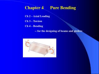
Chapter 4 Pure Bending . Ch 2 – Axial Loading Ch 3 – Torsion Ch 4 – Bending -- for the designing of beams and girders. 4.1 Introduction. A. Eccentric Loading. B. Pure Bending. 4.2 Symmetric Member in Pure Bending. M = Bending Moment. Sign Conventions for M:.

Chapter 4 Pure Bending
E N D
Presentation Transcript
Chapter 4 Pure Bending Ch 2 – Axial Loading Ch 3 – Torsion Ch 4 – Bending -- for the designing of beams and girders
A. Eccentric Loading B. Pure Bending
4.2 Symmetric Member in Pure Bending M = Bending Moment Sign Conventions for M: -- concave upward ⊝ -- concave downward
Force Analysis – Equations of Equilibrium xz = xy = 0 Fx = 0 (4.1) My-axis = 0 (4.2) Mz-axis = 0 (4.3)
4.3 Deformation in a Symmetric Member in Pure Bending Plane CAB is the Plane of Symmetry Assumptions of Beam Theory: 1. Any cross section to the beam axis remains plane 2. The plane of the section passes through the center of curvature (Point C).
The Assumptions Result in the Following Facts: 1. xy = xz = 0 xy = xz = 0 2. y = z = yz = 0 The only non-zero stress:x 0 Uniaxial Stress The Neutral Axis (surface) : x = 0 & x = 0
Line DE (4.4) Where = radius of curvature = the central angle Line JK (4.5) Before deformation: DE = JK Therefore, (4.6)
The Longitudinal Strain x = (4.8) x varies linearly with the distance y from the neutral surface The max value of x occurs at the top or the bottom fiber: (4.9)
4.4 Stresses and Deformation is in the Elastic Range For elastic response – Hooke’s Law (4.11) (4.10) Therefore, (4.12)
Based on Eq. (4.1) (4.1) (4.12) Hence, (4.13)
Therefore, Within elastic range, the neutral axis passes through the centroid of the section. According to Eq. (4.3) (4.3) and (4.12) It follows or (4.14)
Since Eq. (4.24) can be written as Elastic Flexure Formula (4.15) At any distance y from the neutral axis: Flexural Stress (4.16)
If we define (4.17) Eq. (4.15) can be expressed as (4.18)
Solving Eq. (4.9) (4.9) Finally, we have (4.21)
4.5 Deformation in a Transverse Cross Section Assumption in Pure Bending of a Beam: The transverse cross section of a beam remains “plane”. However, this plane may undergo in-plane deformations. A. Material above the neutral surface (y>0), Since (4.8) Hence, (4.22) Therefore,
B. Material below the neutral surface (y<0), As a consequence, Analogous to Eq. (4.8) For the transverse plane:
= radius of curvature, 1/ = curvature (4.23)
4.6 Bending of Members Made of Several Materials (Composite Beams) From Eq. (4.8) For Material 1: For Material 2:
Notes: 1. The neutral axis is calculated based on the transformed section. 2. 3. I = the moment of inertia of the transformed section 4. Deformation --
Beam with Reinforced Members: As = area of steel, Ac = area of concrete Es = modulus of steel, Ec = modulus of concrete n= Es/Ec
Beam with Reinforced Members: As = area of steel, Ac = area of concrete Es = modulus of steel, Ec = modulus of concrete n= Es/Ec determine the N.A.
4.13 Unsymmetric Bending -- Two planes of symmetry y – axis & z-axis -- Single plane of symmetry – y-axis --M coincides with the N.A.
For an arbitrary geometry + M applies along the N.A (the Centroid = the N.A.) (4.1) Fx = 0 (moment equilibrium) (4.2) My = 0 Mz = 0 (moment equilibrium) (4.3) Substituting into Eq. (4.2)
We have (knowing m/c = constant) or Iyz = 0 indicates that y- and z-axes are the principal centroid of the cross section. Hence, the N.A. coincides with the M-axis. If the axis of M coincides with the principal centroid axis, the superposition method can be used.
= Case A = + Case B For Case A (4.53) (4.54) For Case B For the combined cases : (4.55)
The N.A. is the surface where x = 0. By setting x = 0 in Eq. (4.55), one has Solving for y and substituting for Mz and My from Eq. (4.52), (4.56) This is equivalent to The N.A. is an angle from the z-axis: (4.57)
4.14 General Case of Eccentric Axial loading (4.58) (4.58)
4.15 Bending of Curved Members After bending Before bending Length of N.A. before and after bending (4.59) (4.60) The elongation of JK line Since (4.61) We have
If we define - = and knowing R = R , thus (4.62) Based on the definition of strain, we have (4.63) Substituting into the above equation, (4.64) Also, x = E x (4.65)
Plotting x is not a linear function of y. Since y = R – r, therefore, Substituting this eq. into Eq. (4.1) and or
Therefore, R can be determined by the following equation: (4.66) Or in an alternative format: The centroid of the section is determined by (4.67) (4.59) Comparing Eqs. (4.66) and (4.67), we conclude that: The N.A. axis does not pass through the Centroid of the cross section.
Mz = M Since , it follows or Recalling Eqs. (4-66) and (4.67), we have Finally, (4.68)
By defining , the above equation takes the new form (4.69) Substituting this expression into Eqs. (4.64) and (4-65), we have and (4.70, 71) Determination of the change in curvature: From Eq. (4.59) Since and from Eq. (4.69), one has
Hence, the change of curvature is (4.72) End of Ch 4
1 2