Download

1 / 36
400 likes | 771 Vues
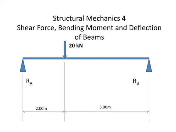
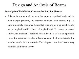
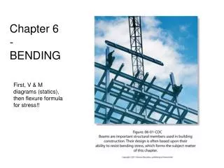
Chapter 5 Analysis and Design of Beams for Bending . 5.1 Introduction. -- Dealing with beams of different materials: steel, aluminum, wood, etc. -- Loading: transverse loads Concentrated loads Distributed loads. -- Supports Simply supported Cantilever Beam

E N D
5.1 Introduction -- Dealing with beams of different materials: steel, aluminum, wood, etc. -- Loading: transverse loads Concentrated loads Distributed loads
-- Supports Simply supported Cantilever Beam Overhanging Continuous Fixed Beam
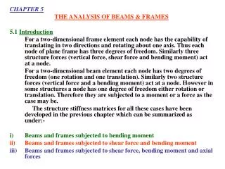
A. Statically Determinate Beams -- Problems can be solved using Equations of Equilibrium B. Statically Indeterminate Beams -- Problems cannot be solved using Eq. of Equilibrium -- Must rely on additional deformation equations to solve the problems. FBDs are sometimes necessary:
FBDs are necessary tools to determine the internal (1) shear force V – create internal shear stress; and (2) Bending moment M – create normal stress From Ch 4: (5.1) (5.2) Where I = moment of inertia y = distance from the N. Surface c = max distance
Recalling, elastic section modulus,S = I/c, (5.3) hence For a rectangular cross-section beam, (5.4) From Eq. (5.3),max occurs at Mmax It is necessary to plot the V and M diagrams along the length of a beam. to know where Vmaxor Mmax occurs!
5.2 Shear and Bending-Moment Diagrams • Determining of V and M at selected points of the beam
Sign Conventions • The shear is positive (+) when external forces acting on the beam tend to shear off the beam at the point indicated in fig 5.7b 2. The bending moment is positive (+) when the external forces acting on the beam tend to bend the beam at the point indicated in fig 5.7c Moment
5.3 Relations among Load, Shear and Bending Moment • Relations between Load and Shear Hence, (5.5)
Integrating Eq. (5.5) between points C and D (5.6) VD – VC = area under load curve between C and D (5.6’) 1 (5.5’)
Relations between Shear and Bending Moment or (5.7)
(5.7) MD – MC = area under shear curve between points C and D
5.4 Design of Prismatic Beams for Bending -- Design of a beam is controlled by |Mmax| (5.1’,5.3’) Hence, the min allowable value of section modulus is: (5.9)
Question: Where to cut? What are the rules? Answer: whenever there is a discontinuity in the loading conditions, there must be a cut. Reminder: The equations obtained through each cut are only valid to that particular section, not to the entire beam.
5.5 Using Singularity Functions to Determine Shear and Bending Moment in a Beam Beam Constitutive Equations
Notes: • In this set of equations, +y is going upward • and +x is going to the right. • 2. Everything going downward is “_”, and upward • is +. There is no exception. • 3. There no necessity of changing sign for an y • integration or derivation. • Sign Conventions: • 1. Force going in the +y direction is “+” • 2. Moment CW is “+”
Rules for Singularity Functions Rule #1: (5.15) (5.14)
Rule #2: • Distributed load w(x) is zero order: e.g. wo<x-a>o • 2. Pointed load P(x) is (-1) order: e.g. P<x-a>-1 • 3. Moment M is (-2) order: e.g. Mo<x-a>-2
Rule #4: • Set up w = w(x) first, by including all forces, from the left to the right of the beam. • Integrating w once to obtain V, w/o adding any constants. • Integrating V to obtain M, w/o adding any constants. • Integrating M to obtain EI , adding an integration constant C1. • Integrating EI to obtain EIy, adding another constant C2. • 6. Using two boundary conditions to solve for C1 and C2.
After integration, and observing that We obtain as before (5.11) (5.12) (5.13)
(5.16) and (5.17)