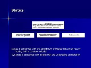
Engineering Mechanics: Statics
Engineering Mechanics: Statics . Chapter 2: Force Systems. Force Systems. Part A: Two Dimensional Force Systems. Force. An action of one body on another Vector quantity External and Internal forces Mechanics of Rigid bodies: Principle of Transmissibility

Engineering Mechanics: Statics
E N D
Presentation Transcript
Engineering Mechanics: Statics Chapter 2: Force Systems
ForceSystems Part A: Two Dimensional Force Systems
Force An action of one body on another Vector quantity External and Internal forces Mechanics of Rigid bodies: Principle of Transmissibility Specify magnitude, direction, line of action No need to specify point of application Concurrent forces Lines of action intersect at a point
Vector Components • A vector can be resolved into several vector components • Vector sum of the components must equal the original vector • Do not confused vector components with perpendicular projections
Rectangular Components • 2D force systems • Most common 2D resolution of a force vector • Express in terms of unit vectors , y q x Scalar components – can be positive and negative
Rectangular components are convenient for finding the sum or resultant of two (or more) forces which are concurrent Actual problems do not come with reference axes. Choose the most convenient one! 2D Force Systems
Example 2.1 • The link is subjected to two forces F1 and F2. Determine the magnitude and direction of the resultant force. Solution
Example 2/1 (p. 29) Determine the x and y scalar components of each of the three forces
y x Rectangular components • Unit vectors • = Unit vector in direction of qy qx
Problem 2/4 • The line of action of the 34-kN force runs through the points A and B as shown in the figure. • (a) Determine the x and y scalar component of F. • (b) Write F in vector form.
Moment • In addition to tendency to move a body in the direction of its application, a force tends to rotate a body about an axis. • The axis is any line which neither intersects nor is parallel to the line of action • This rotational tendency is known as the momentM of the force • Proportional to force F and the perpendicular distance from the axis to the line of action of the force d • The magnitude of Mis M = Fd
Moment • The moment is a vector M perpendicular to the plane of the body. • Sense of M is determined by the right-hand rule • Direction of the thumb = arrowhead • Fingers curled in the direction of the rotational tendency • In a given plane (2D),we may speak of moment about a point which means moment with respect to an axis normal to the plane and passing through the point. • +, - signs are used for moment directions – must be consistent throughout the problem!
Moment • A vector approach for moment calculations is proper for 3D problems. • Moment of F about point A maybe represented by the cross-product where r = a position vector from point A to any point on the line of action of F M = r x F M = Fr sin a = Fd
Example 2/5 (p. 40) Calculate the magnitude of the moment about the base point O of the 600-N force by using both scalar and vector approaches.
Problem 2/43 (a) Calculate the moment of the 90-N force about point O for the condition q = 15º. (b) Determine the value of q for which the moment about O is (b.1) zero (b.2) a maximum
Couple • Moment produced by two equal, opposite, and noncollinear forces = couple • Moment of a couple has the same value for all moment center • Vector approach • Couple M is a free vector M = F(a+d) – Fa = Fd M = rA x F + rB x (-F) = (rA-rB) x F = r x F
Couple • Equivalent couples • Change of values F and d • Force in different directions but parallel plane • Product Fd remains the same
Force-Couple Systems • Replacement of a force by a force and a couple • Force F is replaced by a parallel forceFand a counterclockwise couple Fd • Example Replace the force by an equivalent system at point O • Also, reverse the problem by the replacement of a force and a couple by a single force
Problem 2/67 The wrench is subjected to the 200-N force and the force P as shown. If the equivalent of the two forces is a for R at O and a couple expressed as the vector M = 20 kN.m, determine the vector expressions for P and R
Resultants • The simplest force combination which can replace the original forces without changing the external effect on the rigid body • Resultant = a force-couple system
Resultants • Choose a reference point (point O) and move all forces to that point • Add all forces at O to form the resultant force R and add all moment to form the resultant couple MO • Find the line of action of R by requiring R to have a moment of MO
Problem 2/79 Replace the three forces acting on the bent pipe by a single equivalent force R. Specify the distance x from point O to the point on the x-axis through which the line of action of R passes.
ForceSystems Part B: Three Dimensional Force Systems
Three-Dimensional Force System • Rectangular components in 3D • Express in terms of unit vectors , , • cosqx, cosqy , cosqz are the direction cosines • cosqx = l, cosqy = m, cosqz= n
Three-Dimensional Force System • Rectangular components in 3D • If the coordinates of points A and B on the line of action are known, • If two angles q and f which orient the line of action of the force are known,
Problem 2/98 • The cable exerts a tension of 2 kN on the fixed bracket at A. Write the vector expression for the tension T.
Three-Dimensional Force System • Dot product • Orthogonal projection of Fcosa of F in the direction of Q • Orthogonal projection of Qcosa of Q in the direction of F • We can express Fx = Fcosqx of the force F as Fx = • If the projection of F in the n-direction is
Example • Find the projection of T along the line OA
Moment and Couple • Moment of force F about the axis through point O is • r runs from O to any point on the line of action of F • Point O and force F establish a plane A • The vector Mo is normal to the plane in the direction established by the right-hand rule • Evaluating the cross product MO = r x F
Moment and Couple • Moment about an arbitrary axis known astriple scalar product (see appendix C/7) • The triple scalar product may be represented by the determinant where l, m, n are the direction cosines of the unit vector n
Sample Problem 2/10 A tension T of magniture 10 kN is applied to the cable attached to the top A of the rigid mast and secured to the ground at B. Determine the moment Mz of T about the z-axis passing through the base O.
Resultants • A force system can be reduced to a resultant force and a resultant couple
Wrench Resultants • Any general force systems can be represented by a wrench
Problem 2/143 • Replace the two forces and single couple by an equivalent force-couple system at point A • Determine the wrench resultant and the coordinate in the xy plane through which the resultant force of the wrench acts
Resultants • Special cases • Concurrent forces – no moments about point of concurrency • Coplanar forces – 2D • Parallel forces (not in the same plane) – magnitude of resultant = algebraic sum of the forces • Wrench resultant – resultant couple M is parallel to the resultant force R • Example of positive wrench = screw driver
Problem 2/142 • Replace the resultant of the force system acting on the pipe assembly by a single force R at A and a couple M • Determine the wrench resultant and the coordinate in the xy plane through which the resultant force of the wrench acts