Comprehensive Overview of Target Tracking in Radar Systems
Understand the principles and techniques of target tracking in radar systems, including single and multiple target tracking methods, such as sequential lobing and monopulse. Learn about range tracking, error signals, and Matlab code implementations.

Comprehensive Overview of Target Tracking in Radar Systems
E N D
Presentation Transcript
Mohammed Soud Mohareb 120051649 Mohammed Ismail Al- Feqawi 120050676 Target tracking
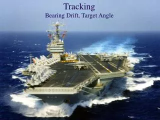
1. Introduction • Tracking radar systems are used to measure the targets range, azimuth angle, elevation angle, and velocity • Predict the future values • Target tracking is important to military and civilian purposes as missile guidance and airport traffic control
Target tracking Targets are divided to two types: 1- Single target 2- Multiple targets
Single target 1- Angle tracking A- Sequential lobing B- Conical scan C- Amplitude compression monopulse D- Phase compression monopulse 2- Range tracking
Relation between beamwidth and accuracyAntennas with wide beamwidth are less accuracy than antennas with narrow beam
Line of Sight (LOS) axisThe LOS is called the radar tracking axis too
Error signal • Describes how much the target has deviated from the beam main axis • Radar trying to produce a zero error signal • Azimuth and elevation error
1. Sequential lobing • Sequential lobing is often referred to as lobe switching or sequential switching • Accuracy depends on the pencil beam width • It is very simple to implement
Concept of operation: • Measuring the difference between the echo signals voltage levels
1- When the target being on the LOSThe difference between the echo signals voltage in (A) and (B) equal zero, that’s mean zero error signal
2. When the target being off the LOSSignal in position(A) will attenuate more than signal in position(B) , that’s mean a nonzero error signal
2. Conical scan- It’s an extension of sequential lobbing- The feed of antenna is rotating around the antenna axis
- The envelope detector is used to extract the return signal amplitude- AGC is used to reduce the echo signal amplitude if it is strong and raises it when it is weaker
3. Amplitude compression monopulse • This type is more accurate than sequential and conical scanning • Feed generated four beams simultaneously with single pulse • The four beams are inphase but have different amplitudes.
Four beams shapeFour feeds mainly horns are used to produce the monopulse antenna pattern
Simplified amplitude comparison monopulse radar block diagram
When the target being on the LOSradar compares the amplitudes and phases of all echo signals of target
To move the servosystem on the target we need to calculate Error signal output
Error signal outputTo calcualte the error signal output first we need to calculate azimuth and elevation error
Azimuth and elevation error can be calculated by using Microwave comparator circuitry
4- Phased compression monopulse • It’s the same as the last type but the amplitude here is equal for the four beams with different phases • Phase comparison monopulse tracking radars use a minimum of a two-element array antenna
Range tracking- Target range is measured by estimating the round-trip delay
Split Gate System • It consist of two gates: 1-Early gate 2- Late gate • The early gate produces positive voltage output but the late gate produces negative voltage output. • Subtracting & integration • Output is: zero, negative or positive
Multiple Targets Here the system is more difficult since: • Tracking • Scanning • reporting
Track while scanning (TWS) • This type of radar is used for multiple targets • It scans for new targets while its tracking old targets • When TWS scan a new target it initiates a new track file
Any Tws Radar Make • Target detection • Generation of tracking “Gates” • Target track initiation and track file generation (if a new target) • Correlation • Track gate prediction, smoothing and positioning • Display and future target calculations