Download
1 / 1
80 likes | 479 Vues
TOUGH-FLAC: A Computer Simulator for Analysis of Geomechanical Performance of Geological Carbon Sequestration Systems Jonny Rutqvist Earth Sciences Division, Lawrence Berkeley National Laboratory. Geomechanics of Geological Carbon Sequestration Systems. TOUGH-FLAC Simulator.

E N D
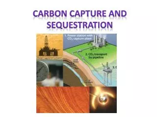
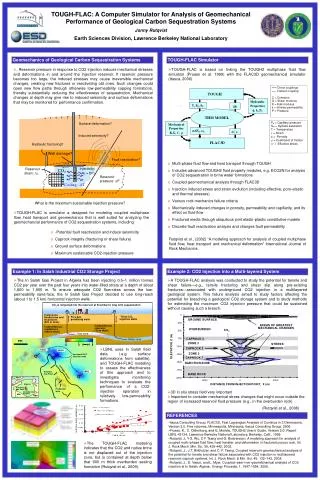
TOUGH-FLAC: A Computer Simulator for Analysis of Geomechanical Performance of Geological Carbon Sequestration Systems Jonny Rutqvist Earth Sciences Division, Lawrence Berkeley National Laboratory Geomechanics of Geological Carbon Sequestration Systems TOUGH-FLAC Simulator • . Reservoir pressure in response to CO2 injection induces mechanical stresses and deformations in and around the injection reservoir. If reservoir pressure becomes too large, the induced stresses may cause irreversible mechanical changes, creating new fractures or reactivating old ones. Such changes could open new flow paths through otherwise low-permeability capping formations, thereby substantially reducing the effectiveness of sequestration. Mechanical changes at depth may give rise to induced seismicity and surface deformations that may be monitored for performance confirmation. • TOUGH-FLAC is based on linking the TOUGH2 multiphase fluid flow simulator (Pruess et al. 1999) with the FLAC3D geomechanical simulator (Itasca, 2006). . • Multi-phase fluid flow and heat transport through TOUGH • Includes advanced TOUGH2 fluid property modules, e.g. ECO2N for analysis of CO2 sequestration in brine water formations • Coupled geomechanical analysis through FLAC3D • Injection induced stress and strain evolution (including effective, poro-elastic and thermal stresses) • Various rock mechanics failure criteria • Mechanically induced changes in porosity, permeability and capillarity, and its effect on fluid flow • Fractured media through ubiquitous joint elasto-plastic constitutive models • Discrete fault reactivation analysis and changes fault permeability • TOUGH-FLAC is simulator a designed for modeling coupled multiphase flow, heat transport and geomechanics that is well suited for analyzing the geomechancial performance of CO2 sequestration systems, including • -Potential fault reactivation and induce seismicity • Caprock integrity (fracturing or shear failure) • Ground surface deformations • Maximum sustainable CO2-injection pressure Rutqvist et al., (2002) “A modeling approach for analysis of coupled multiphase fluid flow, heat transport and mechanical deformation” International Journal of Rock Mechanics. Example 1: In Salah Industrial CO2 Storage Project Example 2: CO2 Injection into a Multi-layered System • The In Salah Gas Project in Algeria has been injecting 0.5–1 million tonnes CO2 per year over the past four years into water-filled strata at a depth of about 1,800 to 1,900 m. To ensure adequate CO2 flow-rates across the low-permeability sand-face, the In Salah Gas Project decided to use long-reach (about 1 to 1.5 km) horizontal injection wells. • A TOUGH-FLAC analysis was conducted to study the potential for tensile and shear failure—e.g., tensile fracturing and shear slip along pre-existing fractures—associated with underground CO2 injection in a multilayered geological system. This failure analysis aimed to study factors affecting the potential for breaching a geological CO2 storage system and to study methods for estimating the maximum CO2 injection pressure that could be sustained without causing such a breach. • LBNL uses In Salah field data (.e.g surface deformations from satellite). and TOUGH-FLAC modeling to assess the effectiveness of this approach and to investigate monitoring techniques to evaluate the performance of a CO2-injection operation in relatively low-permeability formations. • 3D in situ stress field very important • Important to consider mechanical stress changes that might occur outside the region of increased reservoir fluid pressure (e.g., in the overburden rock) (Rutqvist et al., 2008) REFERENCES • Itasca Consulting Group, FLAC3D, Fast Lagrangian Analysis of Continua in 3 Dimensions, Version 2.0. Five volumes, Minneapolis, Minnesota, Itasca Consulting Group, 2006. • Pruess, K., C. Oldenburg, and G. Moridis, TOUGH2 User’s Guide, Version 2.0, Report LBNL-43134, Lawrence Berkeley National Laboratory, Berkeley, Calif., 1999 • Rutqvist, J, Y-S. Wu, C-F Tsang and G. Bodvarsson. A modeling approach for analysis of coupled multi¬phase fluid flow, heat transfer, and deformation in fractured porous rock, Int. J. Rock Mech. Min. Sci. 39, 429-442, 2002. • Rutqvist, J., J.T. Birkholzer, and C.-F. Tsang, Coupled reservoir-geomechanical analysis of the potential for tensile and shear failure associated with CO2 injection in multilayered reservoir-caprock systems. Int. J. Rock Mech. & Min. Sci, 45, 132–143, 2008. • Rutqvist, J., D. Vasco, and L. Myer, Coupled reser¬voir-geomechanical analysis of CO2 injection at In Salah, Algeria.. Energy Procedia, 1, 1847-1854, 2009. • The TOUGH-FLAC modeling indicates that the CO2 and native brine is not displaced out of the injection zone, but is contained at depth below that 900 m thick overburden sealing formation (Rutqvist et al., 2009).