Controlling the World with Raspberry Pi
740 likes | 899 Vues
Controlling the World with Raspberry Pi. J Dean Brock, Rebecca Bruce, and Marietta E. Cameron IEEE Southeast Conference 2014. Workshop Materials. All workshop materials are available on our RPi webserver: pinkie-pie.cs.unca.edu Also backed up on the UNCA CS webserver:

Controlling the World with Raspberry Pi
E N D
Presentation Transcript
Controlling the World with Raspberry Pi J Dean Brock, Rebecca Bruce, and Marietta E. Cameron IEEE Southeast Conference 2014
Workshop Materials • All workshop materials are available on our RPi webserver: pinkie-pie.cs.unca.edu • Also backed up on the UNCA CS webserver: www.cs.unca.edu/pinkie-pie
Rapberry Pi Model B Picture from Wikimedia
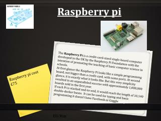
Raspberry Pi history • A computer to inspire children • to put the fun back into learning computing • provide computers to the poor • guided by Raspberry Pi foundation • Early support from academia and industry • University of Cambridge Computer Laboratory • Broadcom • Raspberry Pi model B launched in early 2012 • Model A is $10 cheaper
A Headless Connection • Fine for embedded systems applications, web server, home router, network and sensors (monitoring), etc. • Requires personal computer setup • Install a terminal emulator or ssh client for Windows • MobaXterm • PuTTY • or something else
Raspberry Pi Quick start From Raspberry Pi Quick start guide
Raspberry Pi hardware • Broadcom BCM2835 SoC (system on chip) • 700 MHz ARM1176JZF-S CPU • ARM11 microarchitecture with ARMv6A ISA • Video Core IV GPU (1080p, 24GFLOPS) • Peripherals: UART, USB, I2C, GPIO • LAN9512 USB hub and Ethernet controller • 512 Mbytes RAM • Connectors: USB, Ethernet, HDMI, camera • SD-card
Very detailed references • Schematics for Rasberry Pi board • BCM2835 ARM peripherals data sheet • LAN9512 data sheet • ARMv6 architecture reference manual • Available with ARM login id • Or search using google • Almost 400 pages
Distros • Consult the lists • Raspberry Pi foundation list • Embedded Linux list • Or purchase a preformatted card • We are using Raspbian • A variation of the wheezy release of debian • Students may have strong opinions • It won’t hurt to let them have their way
Formatting the SD card • You really need to follow the directions • Of course, you also have to choose wisely • dd is old fashioned command-line program • but it works on Linux and Mac OS • We use a shell script that calls dd • Win32DiskManager is fine for Windows • Allocate plenty of time
Connecting • With a monitor • Nothing to it • Headless • Secure Shell (ssh) • IP assigned by DHCP • Use your router administrative page • Run tail on /var/log/messages • Serial-Connection • Use a serial cable connection and connect like you did in 1988
First Connection • raspi-config starts automatically • Login as use “pi” • With password “raspberry • Your next steps • Expand the root file system • Change the password • Get the right internationalisation • Reboot
Second boot • Update your distribution • apt-get update • apt-get upgrade • You will want to install additional software • sudo apt-get install emacs python-pyside… • Create your own account • Be prepared to wait • SD Cards are “classed” by write speed • Sometimes it takes a while to save a file
A Serial Connection to the Pi • The Physical Connection: • Plug in the power supply • Grab (1) breadboard, (1) 3.3V FTDI cable, (1) 6-pin header, (1) Pi cobbler and ribbon cable, and (3) wires to create the physical connection shown on the next slide. • To implement a 3-wire TTL RS-232 connection to your Pi, you’ll connect ground to ground and RX to TX in both directions.
Physical Serial Connection The colored wire-must connect to pin 1 on the Pi DETAIL: Connect ground to ground and RX to TX in both directions: Connect FTDI yellow to Pi TX Connect FTDI orange to Pi RX Connect Gnd to Gnd via the power rail
The Software Serial Connection • On Windows, useMobaXterm or PuTTY to connect to the Pi with these RS-232 settings: • Baud: 115200 • Data: 8-bit • Parity: none • Stop bits: 1 • Flow control: none • On Linux use screen to connect to the serial device. • Make sure your Pi has power!
MobaXterm Select: Sessions->Serial Choose COM port Set Baud rate
PuTTY • Use PuTTY with the following settings.
A Linux Serial Connection • First, determine the name of the serial device that is connected to the Pi. It is probably something like/dev/ttyUSBN. • Connect to it with the following command:screen /dev/ttyUSBN 115200 • Hit Enter a couple of times and hopefully the Pi will give you a login prompt. • Use the two-character sequence CTRL+A k to exit from screen.
Login to the Pi • Account name: pi • Password: creative Hit the enter key a couple of times to initiate the prompt
Linux Try it out:
Raspberry Pi GPIO A subset of the BCM2835 GPIO pins
RPi General Purpose IO (GPIO) Pins • 17 GPIO pins on the P1 header • most have alternated functions • two pins for UART; two for I2C; six for SPI • All 17 pins can be GPIO (i.e., INPUT or OUTPUT) • all support interrupts • internal pull-ups & pull-downs for each pin • I2C pins have onboard pull-ups • using them for GPIO may not work • Pins are 3.3V not 5V like on the Arduino • They are connected directly to the Broadcom chip • Sending 5V to a pin may kill the Pi • Maximum permitted current draw from a 3.3V pin is 50mA
The Bigger Picture Diagram includes BCM GPIO references (GPIO.BCM), common functions, WiringPi pin references, and Pin numbers (GPIO.BOARD)
Using the GPIO Pins • There are two methods to read or write these pins • File-type access in userspace • accessed through the device (/dev) interface • Write/read memory addresses allocated to the GPIO peripheral of the SoC • Memory locations can be found in the datasheet for the BCM2835 • You can use the WiringPi library to help with both
Blinking LED: Physical Connection • Connect an LED to GPIO 17 (P1-11) • The LED will initially be off because the GPIO pins are initialized as inputs at power-on (except for TXD).
Blinking LED: Software Solution 1 • Using a file-type access • Run shell script blink.sh • cd examples • sudo./blink.sh #!/bin/shecho 17 > /sys/class/gpio/exportecho out > /sys/class/gpio/gpio17/directionwhile truedo echo 1 > /sys/class/gpio/gpio17/value sleep 1 echo 0 > /sys/class/gpio/gpio17/value sleep 1done • “Close” the /sys/class/gpio/gpio17 directory: • echo 17 > /sys/class/gpio/unexport
More Details • Create a shell script using nano: • Change the permissions on blink.sh: chmod 755 blink.sh • Run blink.sh: sudo ./blink.sh (in directory where blink.sh is stored) • After running the script your LED should be blinking endlessly. Give the command: Ctrl-c Ctrl-cto abort the script • All of the commands in the script can be issued one at a time on the command line; beginning by giving the commands: sudo -ito run a root shell---notice the change in the prompt • Look at the files and their contents in directory /sys/class/gpio/ and its subdirectories --- see next slide
Understanding /sys/class/gpio/ • In Linux, everything is a file: /dev/ttyUSB0, /sys/class/net/eth0/address, /dev/mmcblk0p2,… • sysfsis a kernel module providing a virtual file system for device access at /sys/class • provides a way for users (or code in user-space) to interact with devices at the system (kernel) level • A demo • Advantages / Disadvantage • Allows conventional access to pins from userspace • Always involves mode switch to kernel, action in kernel, mode switch back to user, and could have a context switch • Slower than digitalWrite()/digitalRead() of Arduino • with less predictable response times
A C program to do the same thing • GPIO with sysfs on Raspberry Pi (Part 2) • Code on Github • Beware: the code assumes a Rev1 pinout
Introducing the WiringPi library • A GPIO access library written in C for the BCM2835 • Writes/reads the addresses of the memory allocated to the GPIO • Used to make common IO operations easier • Similar to the Wiring library in the Arduino • Features: • command-line utility gpio • supports analog reading and writing • More • Install the Wiring Pi library following these instructions • Already installed on your Pi
Wiring Pin Numbers WiringPi Pin numbers Image credit: https://projects.drogon.net/raspberry-pi/wiringpi/pins/
Software Solution 2: WiringPi #include <stdio.h> #include <wiringPi.h> // LED Pin - wiringPi pin 0 is BCM_GPIO 17. #define LED 0 int main (void) { printf ("Raspberry Pi blink\n") ; wiringPiSetup () ; // note the setup method chosen pinMode (LED, OUTPUT) ; for (;;) { digitalWrite (LED, HIGH) ; // On delay (500) ; // mS digitalWrite (LED, LOW) ; // Off delay (500) ; } return 0 ; } • blink.c is an example provided with the wiringPi library • cd to examples or wiringPi/examples
Running blink.c • Compile and run the blink program gcc-Wall -o blink blink.c -lwiringPi compile sudo./blink run • Runs forever • kill ctrl-c ctrl-c • Note: One of the four wiring setupfunctionsmust be called at the start of your program or your program will not work correctly
Input Example • Physical Connection: Add a push-button switch to GPIO 22
Input Example Software • Look in examples directory for button.c • Compile and run the button program gcc-Wall -o button button.c-lwiringPi compile sudo./button run • The push-button controls the LED • Runs forever • kill with ctrl-c ctrl-c
button.c #include <stdio.h> #include <wiringPi.h> // LED Pin - wiringPi pin 0 is BCM_GPIO 17 #define LED 0 // LED Pin - wiringPi pin 3 is BCM_GPIO 22 #define BUTTON 3 int main (void) { printf ("Raspberry Pi Push-Button Controlled LED\n"); wiringPiSetup (); pinMode (LED, OUTPUT); pinMode (BUTTON, INPUT); pullUpDnControl (BUTTON, PUD_UP); // using a pull-up resistor for(;;) { if ( digitalRead (BUTTON) == HIGH ) { digitalWrite (LED, LOW); } else { digitalWrite (LED, HIGH); } delay (1); } }
Just for Fun try Music • Physical Connection: Remove the push-button & Replace the LED with a speaker
Just for Fun try Music • Software • Look in examples directory for music.c&pitches.h • Compile and run the program gcc -Wall -o music music.c -lwiringPi sudo./music • Could add an amplifier but not today
I2C – Inter-Integrated Circuit • Invented by Phillips in 1982 • I2C specification • A tradeoff between speed and area • Less spaces devoted to wires • Fewer wires can decrease throughput • A good idea for sensors • But not for disk drives • Adopted by Intel for personal computers • Under the name SMBus • 00:1f.3 SMBus: Intel Corporation 82801JD/DO (ICH10 Family) SMBus Controller (rev 02)
I2C • Understanding I2C • The physical I2C bus • Masters and Slaves • The physical protocol • I2C device addressing • The software protocol • I2C support in Linux kernel • And Windows and Arduino • And Microcontrollers and … • A good Tutorial at Robot Electronics Image credit: http://quick2wire.com/articles/i2c-and-spi/
The physical I2C bus • Two wires: SCL and SDA • SCL is the clock line: used to synchronize all data transfers • SDA is the data line • Both SCL and SDA lines are "open drain" drivers • Can only be driven low • For the line to go high provide a pull-up resistors to Vcc • The value of Vcc is an example of something SMBus restricts Image credit: http://electronics.stackexchange.com/questions/70312/n-ch-fet-with-open-drain-output Image credit: http://www.robot-electronics.co.uk/acatalog/I2C_Tutorial.html
Add the physical I2C devices • Adafruit breakout boards • BMP180 • 9-DOF: L3GD20 and LSM303 • There’s just four connections on each • GND • 3Vo (to 3V3 of T-Cobbler) • SDA • SCL
Masters and Slaves • The devices are either masters or slaves • Master device drives the clock • Master device initiates the transfers • Master device controls the transfer • Typically only one master. • But multi-master mode is possible
The I2C Physical Protocol Wikimedia commons image • Data is transferred in sequences of 8 bits, followed by an acknowledge bit • Bits are sent with the MSB (Most Significant Bit) first. • The SCL line is pulsed high, then low for each bit • The standard clock (SCL) speed for I2C is up to 100KHz • Start and stop sequences mark the beginning and end of a transaction • Transfer is initiated with SDA is pulled low while SCL (clock line) is high • During data transfer, SDA must not change while SCL is high
I2C Device Addressing • I2C addresses are 7 bits or sometimes 10 bits • Up to 128 devices on the usual I2C bus • Devices has fixed addresses • But SMBus supports “address resolution” • Addresses are still sent in 8 bits • Last bit is zero if writing • Last bit is one if reading Image credit: http://www.robot-electronics.co.uk/acatalog/I2C_Tutorial.html
I2C Write Protocol • Send start sequence • Send address of slave address with last bit 0 • Send one byte register number or “command” • It’s a bit more complicated with an EEPROM • Send the data byte • If appropriate send more data • Register number will be incremented • Send stop sequence • No length field!