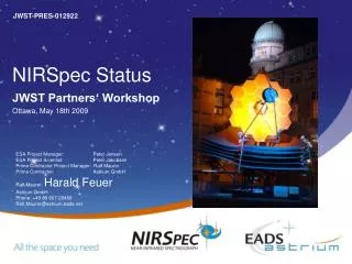
NIRSpec Operations Concept
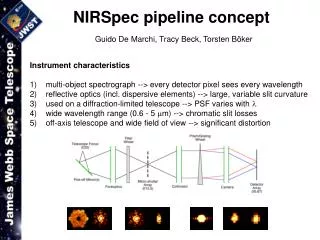
NIRSpec Operations Concept. Michael Regan(STScI), Jeff Valenti (STScI) Wolfram Freduling(ECF), Harald Kuntschner(ECF), Robert Fosbury (ECF). Micro-Shutter Array. Grating/Prism/Mirror Wheel. Detector Array. Filter Wheel. Pick-off Optics. Fore-optics. Collimator. Camera.


NIRSpec Operations Concept
E N D
Presentation Transcript
NIRSpec Operations Concept Michael Regan(STScI), Jeff Valenti (STScI) Wolfram Freduling(ECF), Harald Kuntschner(ECF), Robert Fosbury (ECF)
Micro-Shutter Array Grating/Prism/Mirror Wheel Detector Array Filter Wheel Pick-off Optics Fore-optics Collimator Camera NIRSpec Optical Layout
Target Acquisition • Need to have maximal light from science targets going through all the slits formed by shutters • This requires getting both the correct pointing and the correct roll • After acquisition both the pointing and the roll must be held relatively constant throughout the observation.
Target Location Tolerance • Assure that the ensemble throughput is not reduced by more than 10% for 95% of the observations • Leads to a two sigma error of 25 mas. • Therefore, one sigma we must be within 12 mas of desired location. • Both pointing and roll errors contribute to this error
How do they interact? • Sin(roll_error) < sqrt(12mas2-pointing_error2)/100”
Roll Angle Acquisition • User will be given a range of roll angles after visit has been preliminarily scheduled • User will select a roll and design their shutter mask • Chosen roll angle and shutter mask will be put into visit file • Spacecraft will use star trackers to move telescope to required roll angle
Positional Acquisition • Uncertainties in the locations of stars in the GSC2 are much larger than the required (<10mas) • Have to take acquisition image to get an offset to the correct location.
Microshutter Grid and Point Source Location • Microshutter grid will lead to biases in the centroid of a point source ~14mas. • More sophisticated algorithms can reduce this • Only by dithering one source or using multiple reference objects can this be averaged out. • With 9 targets get final error of 5 mas.
Roll requirement • With a 5 mas positional uncertainty • Allowed roll error is ~15 arcseconds • Even with perfect positional accuracy • Allowed roll error is ~20 arcseconds • Note that this error includes the user’s uncertainty in being able to determine the required roll angle • Therefore, for now, we are assuming that roll will need to be adjusted.
Steps in a Target Acquisition • Assume wheels at home locations or move them: • filter wheel at closed location • grating wheel at mirror location • Turn on calibration lamp • Take image of MSA plane (uncertain mirror location) • 1D – Centroid each fixed slit • Store away the difference between expected and actual position • Turn off lamp • Open all MSA shutters [except those around bright objects in field] • Move filter wheel to requested acquisition filter • Take acquisition images and centroid • Find Dx, Dy, and Droll • Offset pointing and roll to correct location
Contemporaneous Calibrations • After target acquisition • Switch to a long pass filter • Configure MSA for observation • Take a short direct image • This will help pipeline processing • Switch to requested grating/prism • Switch to closed filter wheel • Turn on emission line lamp • Take a wavecal image • Turn off emission line lamp • Switch to filter wheel long pass filter • Begin science exposures
Detector Operations • NIRSpec will be detector noise limited in R>1000 modes • Up-the-ramp/Multiaccum sampling has been shown to be better than Fowler for detector noise limited observations • In addition, up-the-ramp sampling is more robust against cosmic rays
T2 T2 T2 T2 T2 Baseline Readout Mode Signal Level Reset Samples Groups TIME
Electronic Gain • Goal is to have only one gain setting for NIRSpec • Maximum gain is set by Nyquist sampling single sample read noise (~9e-) or ~4 e-/ADU • Would like to be able to use entire full well ~90K -- 200K e- • 16 bit A/D values lead to 64K dynamic range • Saturated values can be reconstructed from early reads in up-the-ramp. • A single gain of 1.5 e- to 2.5 e- will work
Calibration • Assumptions • NIRSpec will have internal line and continuum sources • Line sources will reach required S/N is a 60 sec exposure • There will be NO parallel calibration • Although it should not be ruled out • Wavelength zero point calibration are required every time the grating wheel is moved. • MSA-to-detector calibration is required every time the mirror is moved in.
Monitoring Calibrations • Two types • Parallel Capable (do not require dedicated visit) • Dark current/read noise/gain • Hot pixels • Shutter throughput • Fixed slit throughput • Small scale flat field variations • Dedicated (frequency depends on stability of detectors and geometry of optical bench) • Linearity • Persistence • Geometric distortions • Large scale flat field • Wavelength solution