Download
1 / 51
550 likes | 745 Vues
Introduction to NIRSpec. Michael Regan. JWST Project Manager P. Jensen. Project Scientist P. Jakobsen. Contracts Officer V. D’Hoedt. Admin. Assistant A. Plitzke. Deputy Project Scientist T. Boeker. System Group. Subsystem Expert Group. PA Manager J. van Dooren.

E N D
Introduction to NIRSpec Michael Regan
JWST Project Manager P. Jensen Project Scientist P. Jakobsen Contracts Officer V. D’Hoedt Admin. Assistant A. Plitzke Deputy Project Scientist T. Boeker System Group Subsystem Expert Group PA Manager J. van Dooren Project Control Manager Z. El Hamel Science Support NN NIRSpec Pr. System Engineer G. Bagnasco Ops, SW & Detector System P. Strada Documentation & Conf. Control D. Green Science Operations Team NN MIRI Principal System Engineer A. Marini Electr. System Engineer & AIV P. Rumler Schedule Control J. Molleman Launcher System Engineer P. Rumler Optical System Engineer M. Te Plate Optical Support P. Marenaci (YGT) Mechanism Engineer* B. Henson Mech. Thermal System Engineer J-C. Salvignol * leaving
JWST Architecture Integrated Science Instrument Module (ISIM) Element Optical Telescope Element (OTE) Sunshield Spacecraft Bus Sun
Current Mission Requirements (the TAC will decide anyway…)
Enter NIRSpec NIRSpec: A Pretty Picture is Not Enough
NIRSpec: Thus Spoke ASWG • 3 x 3 arcmin FOV • 1-5 µm coverage • R~1000, R~100 multiplexed • >100 sources simultaneously • Configurable slit width/length • MEMS array preferred
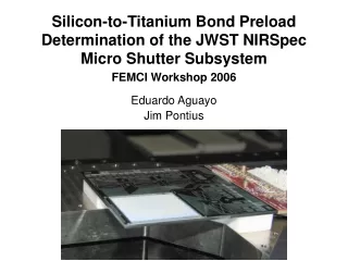
NIRSpec Procurement • Instrument built by European industry under ESA project leadership • Under study since 2001 • Presently entering implementation phase • Two NASA-provided components: • 2 x 2k x 2k HgCdTe Detector Array • 4 x 384 x 185 Micro-Shutter Array
NIRSpec Modes • R=100 (exploratory spectroscopy) • Single prism 0.6 - 5.0 µm • Micro-shutter array or fixed Slits • R=1000 (emission line diagnostics) • 3 gratings 1.0 - 5.0 µm • Micro-shutter array or fixed slit(s) • R=3000 (emission line kinematics) • 3 gratings 1.0 - 5.0 µm • Fixed slit or integral field unit
Wavelength Coverage • R=1000 & R=3000 modes • 1.0 - 5.0 µm • Covered by three overlapping first order gratings: • 1.0 - 1.8 µm • 1.7 - 3.0 µm • 2.9 - 5.0 µm • R=100 mode • 0.6 - 5.0 µm (as NIRCAM) • Covered by single dual-pass prism • Coverage below 1.0 µm is not allowed to drive anything • Resolution to be kept within factor 2 of R=100 1.0 - 5.0 µm • Resolution below 1.0 µm to follow
You Can’t Fight Red shift ! ! NIR MIR
Micro Shutter Array IFU Single 200 mas x 450 mas slits surrounded by 60 mas wide bars >100 objects simultaneously 4 x 384 x 185 Shutters 9 Square Arcmin of MSA Area
A Bit of MEMS History • Initially both Micro Mirrors and Shutters • Mirrors eliminated due to excessive diffraction effects • Initially slit to be made up of several shutters • Later transitioned to “fat MEMS” • Huge simplification of optics • Factor ~4 reduction in MSA array • Reduced slit loss • At expense of multiplexing loss
Diffraction & Slit Loss Spectrograph Entrance Pupil Telescope Exit Pupil Diffracted Output Beam Footprint of PSF
MSA Close-up Key Requirements: Contrast: >2000 (!) Open Fill factor >70% (60 mas bars on 200 mas wide slits)
Integral Field Unit • FOV: 3” x 3” • Sampling: 0.1” • ~30 Slicers • Entirely passive device (no moving parts) • Shuttered by MSA magnet mechanism • Main use R~3000 single object • But R~1000 and R~100 too.... • Superb backup in case of MSA failure • Point and shoot operations
Integral Field Unit Relay optics Slicer Stack (30 slices) Slit mirror Line (30 elements) Pupil mirror Line (30 elements) IFU aperture
Detector Array • 2K4K FPA comprised of two 2K2Ksensor chip assemblies (SCAs) • =0.6–5.0 µm HgCdTe detectors (Rockwell) • FPA passively cooled to T=34–37 K • Key Performance Parameters: • Total noise =6 electrons rms per t=1000 seconds exposure) • QE = >80% • NIRSpec is detector background limited in nearly all modes (!) • Non-stop (“up the ramp”) read and telemetry • 12 s frame time, 1 frame downlink each 50 s
Ha [NII] [NII] Why R=1000? • Science requirement • Clean emission line separation • Main challenge: • [NII] 6548.1 :1 • Ha 6562.8 metallicity diagnostic • [NII] 6583.4 :3 • and also: • [SII] 6716.4 density diagnostic • [SII] 6730.8 R=446 R=319 R=467
Why 200 mas Slit? 1:2 MSA aspect ratio fixed 1.4 µm - Band I 2.4 µm - Band II 4.0 µm - Band III
Why 200 mas Slit? 2 pixels across slit 200 mas optimal?
Optical Schematic 200 mas per 79.5 µm wide shutter 2.52 “/mm, f/12.5 100 mas per 18 µm pixel 5.56 “/mm, f/5.67 1.58 “/mm, f/20
Optical Layout • Buzzwords: • TMA’s • Scheimflug
Focal Plane Layout & Scheimflug NIRCam NIRSpec
SiC The wonder of modern ceramics
WFE at MSA • Requirement: • Diffraction-limited at 2.4 µm • WFE = 180 nm rms or better • 131 nm rms OTE input specified • Fore optics challenging • Relaxation requires degrading sensitivity • Increased slit losses • Reduced photometric accuracy
Ha [NII] [NII] WFE at FPA • Requirement: • Diffraction-limited at 3.0 µm • WFE = 225 nm rms or better • Camera optics challenging • Relaxation requires degrading sensitivity • Larger resolution element • Decreased sensitivity • Jeopardize spectral resolution
NIRSpec Image Quality FPA with Cross-talk PSF at FPA PSF at MSA FPA 100 mas pixels PSF at MSA
Grating Wheel 8 Positions: 1. R=100 Prism 2. Band I R=1000 Grating 3. Band II R=1000 Grating 4. Band III R=1000 Grating 5. Band I R=3000 Grating 6. Band II R=3000 Grating 7. Band III R=3000 Grating 8. Provision for imaging mode
Filter Wheel 8 Positions: 1. Clear Aperture 2. Closed 3. Band I Long Pass l >1.0 µm 4. Band II Long Pass l >1.7 µm 5. Band III Long Pass l >2.9 µm 6. Narrow Band TA l =1.1 µm 7. Broad Band TA 0.9 < l1.1 µm 8. Broad Prism 0.9 < l5 µm Current Issue: Filters in pupil – should they second as pupil stops?
Calibration Unit Carries both continuum and (FP-filtered) line sources
NIRSpec Sensitivity Formal Level I Specs
Target Acquisition Accuracy Goal: 12.5 mas (1s) • Partially documented in gory detail… • NIRSpec Operations Concept • Two dedicated tech notes (more to come)
Image Mode Simulation 2.2 µm Centroid shift!
STScI is currently working on several NIRSpec related studies • MSA planning tool (J. Valenti) • NIRSpec Target Acquisition Alternatives (M. Regan) • What’s in phase 1 and phase 2 with JWST (J. Valenti)
STScI plays a crucial role in NIRSpec • MSA planning tool (J. Valenti) • NIRSpec Target Acquisition Alternatives (M. Regan) • What’s in phase 1 and phase 2 with JWST (J. Valenti) • NIRSpec Calibration Plan ( T. Keyes) • Guide Star Availability and planning (J. Valenti) • Do we use Observing templates? (J. Valenti)