Anomalous Events in Non-Destructive Inspection Data
880 likes | 1.17k Vues
Anomalous Events in Non-Destructive Inspection Data. 18 Dec 2012. Jeremy S. Knopp AFRL/RXCA Air Force Research Laboratory. Disclaimer.

Anomalous Events in Non-Destructive Inspection Data
E N D
Presentation Transcript
Anomalous Events in Non-Destructive Inspection Data 18 Dec 2012 Jeremy S. Knopp AFRL/RXCA Air Force Research Laboratory
Disclaimer • The views expressed in this presentation are those of the author and do not reflect the official policy or position of the United States Air Force, Department of Defense, or the United States Government
Outline • Historical Perspective of Aircraft Structural Integrity Program (ASIP) • Probability of Detection (POD) • Nondestructive Evaluation System Reliability Assessment Handbook (MIL-HDBK-1823A) Revision • Research Objectives to Improve State-of-the-Art POD Evaluation
Aircraft Management Strategies • Safe Life – No Periodic Inspection Required. • Fly a certain number of hours and retire. • Considers the effects of cyclic loading on the airframe with full-scale fatigue test. • For example, testing to 40,000 hours ensures safe life of 10,000 hours. • Used by US Navy. • Damage Tolerance Assessment (DTA) – Periodic Inspection to Detect Damage • Fly and inspect, reassess time to next inspection based on fatigue crack growth analysis, usage, and results of inspection. • Assumes imperfections are present in the early stages of aircraft service. • REQUIRES RELIABLE AND VALIDATED NDI • Used by US Air Force. • Condition-based Maintenance (CBM) – Periodic Inspection and/ or onboard monitoring to Characterize Damage. • Perform repairs only when needed. • Will minimize maintenance costs. • Requires damage characterization, not just detection. • Desired by US Air Force to maximize availability of assets while minimizing sustainment costs. • Condition-based Maintenance (CBM+) – Periodic Inspection to Characterize Damage • – CBM plus prognosis to estimate capability and remaining life for optimal maintenance scheduling.
Provides the engineering discipline and management framework … associated with establishing and maintaining structural safety … in the most cost-effective manner … through a set of defined inspections, repairs, modifications and retirement actions Based on a preventative maintenance strategy that starts in acquisition and continues until retirement The USAF Aircraft Structural Integrity Program (ASIP) ASIP Processes involve engineers and managers working together to control the risks of structural failure
“Wright” approach to Structural Integrity • Approach used by Wright brothers began in 1903. • Essentially the same approach used by USAF for over 50 years. • They performed stress analysis and conducted static tests far in excess of the loads expected in flight. • Safety factor applied to forces that maintained static equilibrium with weight.
B-47 Experience, 1958 • Air Force Strategic Air Command lost two B-47 Bombers on the same day! • Metal fatigue caused the wings on two aircraft to fail catastrophically in flight. • Standard static test and abbreviated flight load survey proved structure would support at least 150% of its design limit load. • No assurance that structure would survive smaller cyclic loads in actual flight.
Aircraft Structural Integrity Program (ASIP) initiated on 12 Jun 1958 with 3 primary objectives: Control structural fatigue in aircraft fleet. Develop methods to accurately predict service life. Establish design and testing methods to avoid structural problems in future aircraft systems. Led to the “safe-life” approach. Probabilistic approach to establishing the aircraft service life capability. Safe-life established by conducting a full-scale airframe fatigue test and dividing the number of successfully test simulated flight hours by a scatter factor (usually 4). ASIP Initiated
Wing separation at ~100 hours (safe-life qualified 4000 hours). Crack initiated from a manufacturing defect. F-111 Experience, 1969 • Two-phase program initiated. • Phase 1 (allow operations at 80% of designed capability) • Material crack growth data collected to develop flaw growth model. • Cold proof test to demonstrate that critical size flaws not present in critical forgings • Improved NDI for use in reinspection • Phase 2 (allow operations at 100% of designed capability) • Incorporated NDI during production. • Used fracture mechanics to determine inspection intervals.
In response to F-111 mishap, ASIP incorporated Damage Tolerance requirements. Objective was to prevent airframe failures resulting from the safe life approach . ASIP provides 3 options to satisfy damage tolerance requirement Slow crack growth (most common option) Fail-safe multiple load path Fail-safe crack-arrest Primary basis for aircraft structure maintenance program for last 30+ years. Inspection requirements based on initial flaw assumptions (slow crack growth) and NDI capability. Today - Inspection burden is increasing due to age of fleet! NDE Research needed to reduce the future maintenance burden. Damage Tolerance Update, 1974
Evolution of Structural Integrity Approaches MIL-STD-1530C Each change was made to enhance our ability to protect structural integrity (prevent structural failures) Today, preventing structural failures requires anticipating events that ensure continuing airworthiness, reliability, availability, and cost-effectiveness
USAF aircraft losses since 1971: 18 due to a structural failure 19 due to a structural failure that was caused by maintenance, pilot error, flight control failures, etc. Next chart plots overall USAF aircraft loss rate from 1947 – 2002 and structures contribution since 1971 Overall loss rate calculated for each year (total losses per year / total fleet flight hours per year) Loss rate due to structures is cumulative since many years without losses due to structural failure USAF Structural Reliability
USAF Structural Reliability 1 C. Babish, “USAF ASIP: Protecting Safety for 50 Years”, Aircraft Structural Integrity Program Conference (2008)
Rare Events • Nov 2, 2007 – Loss of F-15C airplane, 0 casualties • Aircraft operated within limits • Mishap occurred due to a fatigue failure in a forward fuselage single-load-path. • Hot spot missed during design and testing and aggravated by rogue flaw. • NDI can be used to prevent fracture at this hot spot.
Reliability of NDT • Probability of Detection1 • Given a population of cracks of size ‘a’ • geometry, material, orientation, location, … • Given a defined inspection system • POD(a) = Probability that selected cracks of size ‘a’ from the population will be detected • POD(a) = Proportion of all size ‘a’ cracks from the population that would be detected 1 A. P. Berens, NDE Reliability Data Analysis. In American Society for Metals Handbook Vol 17 Nondestructive Evaluation and Quality Control, pp. 689-701. ASM International, 1989.
Reliability of NDT • POD curve • Two parameters • (μ and σ) • μ is a50 • σ describes slope of the curve. Steep curve is ideal. a90 a50 a90/95 or ande
Reliability in NDT • What is ande? • aNDE is the “reliably” detected crack size for the applied inspection system. • Traditionally, reliably detected size has been considered to be the a90 or a90/95 crack size from the estimate of the NDE system POD(a). • Variations of this can be investigated. a90 a50 a90/95 or ande
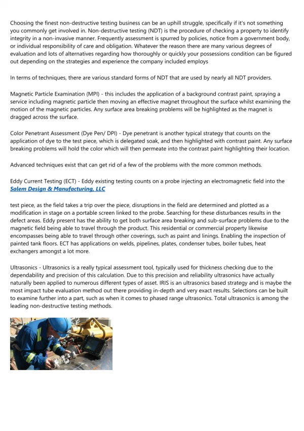
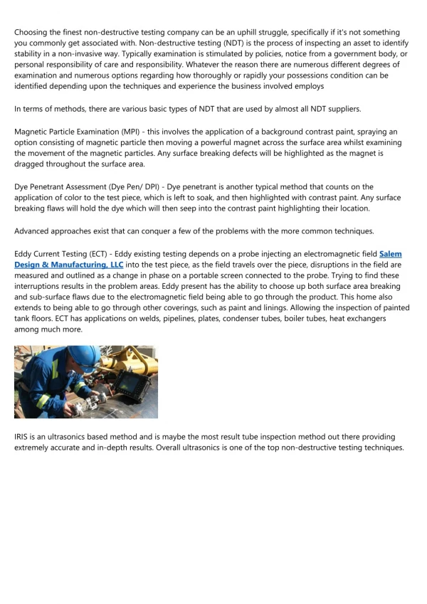
Reliability of NDE • Development of POD was a very important contribution to quantifying performance of NDE • Necessary for effective ASIP program. Damage Tolerance approach requires validated NDE capability. • Quantifying largest flaw that can be missed is important. • Capability of detecting small flaws less important. • First serious investigation • Packman et al 19671 • Four NDI methods (X-ray, dye penetrant, magnetic particle, and ultrasonics) 1 P.F. Packman et al. The applicability of a fracture mechanics – nondestructive testing design criterion. Technical Report AFML-TR-68-32, Air Force Materials Laboratory, USA, May 1968.
Reliability of NDT • Rummel et al 19741 • NASA Space Shuttle Program • Five NDI methods (X-ray, fluorescent penetrant, eddy current, acoustic emission, and ultrasonics) • Lewis et al 19782 (a.k.a – “Have Cracks Will Travel”) • Major US Air Force program to determine reliability. • Perhaps the largest program of this kind in history. • Disappointing results concerning NDI capabiliity. • Both studies inspired more advanced statistical analysis 1 W.D. Rummel et al, The detection of fatigue cracks by nondestructive testing methods. Technical Report NASA CR 2369, NASA Martin Marietta Aerospace, USA, Feb 1974. 2 W.H. Lewis et al, Reliability of nondestructive inspection – final report. Technical Report SA-ALC/MME 76-6-38-1, San Antonio Air Logistics Center, USA, Dec 1978.
Statistical Analysis – POD • Two types of data collected • “Hit/Miss” – binary data in terms of whether or not a flaw is found • “â vs a” – continuous response data has more information (â = signal magnitude, a = size) • Statistical rigor introduced in USAF study conducted by Berens and Hovey in 19811. • Previous analysis methods grouped “hit/miss” data into bins and used binomial statistics to evaluate POD. • Berens and Hovey introduced mathematical model based on log-logistic cumulative distribution function to evaluate POD. This is still standard practice. 1 A.P. Berens and P.W. Hovey, “Evaluation of NDE Reliability Characterization,” AFWAL-TR-81-4160, Vol 1, Air Force Wright- Aeronautical Laboratories, Wright-Patterson Air Force Base, Dec 1981.
Statistical Analysis – POD • Hit/Miss analysis • Sometimes only detection information available (i.e. penetrant testing). Can also be used if constant variance assumption is violated. • Model assumes POD is a function of flaw size. • For logit model (logistic) • For probit model (lognormal) is the standard normal cumulative distribution function. • Maximum likelihood estimates and 1 A. P. Berens, NDE Reliability Data Analysis. In American Society for Metals Handbook Vol 17 Nondestructive Evaluation and Quality Control, pp. 689-701. ASM International, 1989.
Statistical Analysis – POD • Hit/Miss analysis • Unchanged since Berens and Hovey except for confidence bound calculations. • Confidence bound calculations are not available in any commercial software package. • Traditional Wald method for confidence bound calculation is anti-conservative with hit/miss data. • Likelihood ratio method for confidence bound calculation is used in the revised MIL-HNBK-1823A. This is a very complicated calculation. See Annis and Knopp for details1. 1 C. Annis and J.S. Knopp, “Comparing the Effectiveness of a90/95 calculations”, Rev. Prog. Quant. Nondestruct. Eval. Vol 26B pp. 1767–1774, 2007
Statistical Analysis – POD • Hit/Miss analysis • example 1 MIL-HDBK-1823A, Non-Destructive Evaluation System Reliability Assessment (2009).
Statistical Analysis – POD • “â vs a” analysis (â = signal strength, a = flaw size) • Magnitude of signal contains information. • More information results in more statistical confidence, which ultimately reduces sample size requirements. • Again, regression model assumes POD is function of flaw size. • Censored regression almost always involved, so commercial package such as SAS or S-Plus necessary. where, Regression variance 1 MIL-HDBK-1823A, Non-Destructive Evaluation System Reliability Assessment (2009).
Statistical Analysis – POD • â vs a analysis • Basically a linear model. • Wald confidence intervals sufficient. • Delta method used to generate confidence intervals on POD curve.
MIL-HDBK-1823A Summary • Completed in 2007; released in 2009 • 132 pages • All new figures (65) • Approximately 70% new text • Based on best-practices for NDE and statistical analysis • 100% new software available • â vs. a • hit/miss
MIL-HDBK-1823ASupport Website • Download the Handbook • Request the mh1823 POD software http://mh1823.com/mh1823
Addressing Deficiencies (1) • Concern exists on performing a POD calculation on poor data sets • Poor data sets can be defined as: • Limited in sample size • Data does not follow typical POD model fits • Problem when wrong model used for statistical inference • Worst case scenario: a fictitious a90/95 may be obtained. • One possible remedy is a ‘4 parameter model’: • Proposed by Moore and Spencer in 1999, • However, parameter estimation problem difficult using classical statistical methods • It is likely that such methods also require large data sets(Very little work performed to date)
Addressing Deficiencies (2) • Markov-Chain Monte Carlo (MCMC) offers a flexible method to use sampling to calculate confidence bounds. • Bayesian approach with non-informative priors can be used to • Model function: Logit or Probit • Model form: (Parameters): 2, 3, and 4 parameter models. • Upper Bound = P(random missed call) = a • Lower Bound = P(false call rate) = b
Bayesian Approach Prior, “Belief” Physics Based Model Likelihood Posterior Normalizing Constant • Prior – Physics based model or expert opinion • Normalizing Constant : Useful in model selection • Likelihood: forward model and measurement data • Posterior: Integration of information from model and experimental data • y: data • λ : parameter(s)
Bayes Factors for Model Selection Compare two models M2 and M1 Using the Bayes Factor
Difficult Data Set #1 • NTIAC A9002(3)L What’s going on here? NTIAC, Nondestructive Evaluation (NDE) Capabilities Data Book 3rd ed., NTIAC DB-97-02, Nondestructive Testing Information Analysis Center, November 1997
Difficult Data Set #1 • Example of using the wrong model. NTIAC, Nondestructive Evaluation (NDE) Capabilities Data Book 3rd ed., NTIAC DB-97-02, Nondestructive Testing Information Analysis Center, November 1997
Difficult Data Set #1 • 2 parameter logit/probit • Appears to show a90 and a90/95 values â â a (mm) a (mm)
Difficult Data Set #1 • 3 parameter lower logit/probit • Again, appears as if there are a90 and a90/95 values â â a (mm) a (mm)
Difficult Data Set #1 • 3 parameter upper logit/probit â â a (mm) a (mm)
Difficult Data Set #1 • Case study 4 parameter probit â a (mm)
Difficult Data Set #1 • 4 parameter Logit is most likely â a (mm)
Difficult Data Set #1 • Summary of Results
Difficult Data Set #2 • Example of using the wrong model. • Note: MH1823 Software Produce Numerous Warnings. What’s going on here? NTIAC, Nondestructive Evaluation (NDE) Capabilities Data Book 3rd ed., NTIAC DB-97-02, Nondestructive Testing Information Analysis Center, November 1997
Difficult Data Set #2 • 2 parameter logit/probit • Appears to that a90 and a90/95 values exist. â â a (mm) a (mm)
Difficult Data Set #2 • 4 parameter probit • a90 and a90/95 value doesn’t exist â a (mm)
Difficult Data Set #2 • Which model is correct? • Log Marginal Likelihoods and Bayes factors
Small Data Set • A great example where the last procedure fails • Small data sets do not cause any warnings with standard software.
Small Data Set • 4 parameter model â a (inches)
Small Data Set • Summary for Small data set
Conclusion • It sometimes appears (and is desirable) that there is a systematic procedure that will automatically determine the best model, but this actually isn’t the case. • Bayes Factors provide useful approach to evaluate the best model • However, an example with a small data set showed that even the Bayes factor procedure can lead one to a wrong conclusion • It doesn’t tell you to stop and not perform an analysis • Need to look at data and perform ‘diagnostics’ • Bottom line – Procedures don’t replace statisticians.
Model-Assisted POD • C-5 Wing Splice Fatigue Crack Specimens: • Two layer specimens are 14" long and 2" wide, • 0.156" top layer, 0.100" bottom layer • 90% fasteners were titanium, 10% fasteners were steel • Fatigue cracks position at 6 and 12 o’clock positions • Crack length ranged from 0.027" – 0.169“ (2nd layer) • vary: location of cracks – at both 1st and 2nd layer • AFRL/UDRI Acquired Data (Hughes, Dukate, Martin)