Binary Logic (review)
Binary Logic (review). Basic logical operators: (Chapter 7 expanded) NOT AND – outputs 1 only if both inputs are 1 OR – outputs 1 if at lest one input is 1 XOR – outputs 1 if exactly one input is 1. Binary Logic. Logic operators in C : && and

Binary Logic (review)
E N D
Presentation Transcript
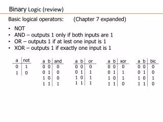
BinaryLogic (review) Basic logical operators: (Chapter 7 expanded) • NOT • AND – outputs 1 only if both inputs are 1 • OR – outputs 1 if at lest one input is 1 • XOR – outputs 1 if exactly one input is 1
Binary Logic Logic operators in C: && and || or ! not (zero word = false, nonzero word = true) Bitwise operators in C: & and | or ~ not ^ xor (each bit in the word is independent)
Uses for Logical Operators • ANDing a bit with 0 produces a 0 at the output while ANDing a bit with 1 produces the original bit. • This can be used to create a mask. • Example: 1011 0110 1010 0100 0011 1101 1001 1010 0000 0000 0000 0000 0000 1111 1111 1111 • The result of ANDing these: 0000 0000 0000 0000 0000 1101 1001 1010 mask: mask last 12 bits
Uses for Logical Operators • ORing a bit with 1 produces a 1 at the output while ORing a bit with 0 produces the original bit. • This can be used to force certain bits of a string to 1s. • For example, 0x12345678 OR 0x0000FFFF results in 0x1234FFFF (e.g. the high-order 16 bits are untouched, while the low-order 16 bits are forced to 1s).
Uses for Logical Operators • XORing a bit with 1 flips the bit (0 -> 1, 1 -> 0) at the output while XORing a bit with 0 produces the original bit.
Uses for Logical Operators • BICing a bit with 1 resets the bit (sets to 0) at the output while BICing a bit with 0 produces the original bit. • This can be used to force certain bits of a string to 0s. • For example, 0x12345678 BIC 0x0000FFFF results in 0x12340000 (e.g. the high-order 16 bits are untouched, while the low-order 16 bits are forced to 0s).
Logical Instructions As we have already discussed, Arm provides the following Boolean (logical) instructions:
Bitwise Instructions ARM a = 0 0 1 1 opcode description b = 0 1 0 1 some common names false 0 0 0 0 false, zero, clear and a and b 0 0 0 1 and orr a or b 0 1 1 1 or, inclusive or bic a and (not b) 0 0 1 0 and-not, inhibit, a>b eor a xor b 0 1 1 0 xor, exclusive or, a!=b mvn not b 1 0 1 0 true 1 1 1 1 true, one, set
Barrel Shifter • The barrel shifter is a functional unit which can be used in a number of different circumstances. • It provides five types of shifts and rotates which can be applied to Operand2: • lsl – logical shift left • lsr – logical shift right • asr – arithmetic shift right • ror – rotate right Note: These are not operations themselves in ARM mode.
Operand 1 Operand 2 BarrelShifter ALU Result Using a Barrel Shifter Register, optionally with shift operation • Shift value can be either be: • 5 bit unsigned integer • Specified in bottom byte of another register. • Used for multiplication by constant Immediate value • 8 bit number, with a range of 0-255. • Rotated right through even number of positions • Allows increased range of 32-bit constants to be loaded directly into registers
Shifts (pp. 98 – 104)) lsl – logical shift left by n bits - 0 enters from right, bits drop off left end – mutiplication by 2n Note: little-endian bit notation 0 … msb lsb a f 5 0 8 9 1 6 10101111010100001000100100010110 gccgenerates lsl lslby 1 becomes for a = a << 1; 01011110101000010001001000101100 5 e a 1 1 2 2 c
Shifts lsr- logical shift right by n bits - 0 enters from left; bits drops off right end – unsigned multiplication by 2n a f 5 0 8 9 1 6 10101111010100001000100100010110 gccgenerates srl lsrby 1 becomes for unsigned int a in 01010111101010000100010010001011 a = a >> 1; 5 7 a 8 4 4 8 b 0 … lsb msb
Shifts asr – arithmetic shift right by n bits - sign bit replicated on left, bits drop off right end – signed division by 2n … lsb sign a f 5 0 8 9 1 6 10101111010100001000100100010110 gccgenerates asr asrby 1 becomes for int variable a in 11010111101010000100010010001011 a = a >> 1; d 7 a 8 4 4 8 b
Shifts lsl and lsr in ARM MOV r4, r6, LSL #4 /* r4 = r6 << 4*/ MOV r4, r6, LSR #8 /* r4 = r6 >> 8 */ MOV r4, r6, LSL r3 /* r4 = r6 << value specified in r3 */ Also possible to shift by the value of a register MOV r4, r6, LSL r3 /* r4 = r6 << value specified in r3 */
Shifts • a shift right has a choice of what to put in the most significant bit (i.e., the sign bit) from the left: either zeros or replicating the sign bit; that is why there are two shift right opcodes • a shift left has no choice as to what will go into the sign bit - it has to be one of the bits already in the register, which is determined by the shift amount; zeros always come into the least significant bit on the right
Shifts Multiplication by small constants (pp. 107 – 108)) Multiplying by a small constant is often faster using shifts and additions. convert the constant into a sum of powers of two (can allow a subtract) convert the multiplications by powers of two into left shifts x * 10 = x * (8 + 2) = (x * 8) + (x * 2) = (x << 3) + (x << 1) x * 20 = x * (16 + 4) = (x * 16) + (x * 4) = (x<<4)+(x<<2) x * 15 = x * (16 - 1) = (x * 16) - x = (x << 4) - x
Shifts Multiplication by small constants (cont’d) x * 10 = x * (8 + 2) = (x * 8) + (x * 2) = (x << 3) + (x << 1) mov r1, r0, lsl #3 /* r1 = r0 * 8 */ add r1, r1, r0, lsl #1 /* r1 = r1 + r0 * 2 */ x * 20 = x * (16 + 4) = (x * 16) + (x * 4) = (x<<4)+(x<<2) mov r1, r0, lsl#4 /* r1 = r0 * 16 */ addr1, r1, r0, lsl#2 /* r1 = r1 + r0* 4*/ Why have add in the above examples? Because only the second source operand can be shifted.
Constant Multiplication • Constant multiplication with subtractions x * 7 = x * (8 – 1) = 8x – x mul r1, r0, #7 /* r1 = r0 * 7 */ is the same as: rsb r1, r0, r0, lsl #3 /* r1 = 8*r0 – r0 = 7*r0 */ rsb r1, r0, r1 is the same as sub r1, r1, r0 /* r1 = r1 – r0 */ rsbrd, rn, op2 (reverse subtract) – subtracts rn from op2.
Constant Multiplication Division (p. 108) MOV r1, r3, ASR #7 ; r1 = r3/128 vs. MOV r1, r3, LSR #7 ; r1 = r3/128 The first treats the registers like signed values (shifts in MSB). The latter treats data like unsigned values (shifts in 0). intvs unsigned int>>
Bitwise Rotation • A bitwise rotation (or circular shift) is a shift operator that shifts all bits of its operand. • Unlike an arithmetic shift, a rotate does not preserve a number's sign bit or distinguish a number's exponent from its mantissa. • Unlike a logical shift, the vacant bit positions are not filled in with zeros but are filled in with the bits that are shifted out of the sequence.
Bitwise Rotation in ARM • ror– rotates right by #n bits; valid range for #n: 1 - 31 … lsb msb n 32-n n 32-n
Bitwise Rotation in ARM Example: mov r4, r6, ror#12 /* r4 = r6 rotated right 12 bits */ Note: r4 = r6 rotated left by 20 bits (32 -12) Therefore there is no need for rotate left operation.
Application of Bit Operations: Field Extraction & Insertion Field extraction with a bit mask - field already in rightmost bits bit mask - a word where bits are used to zero out or select portions of another word assume we are working with nibbles (4-bit fields) remove (clear) all other bits and work with only the low four bits (the mask will have 0s in all the bit positions we wish to clear and 1s in the bit positions we wish to select) xxxxxxxxxxxxxxxxxxxxxxxxxxxxzzzzr0 and 0000 0000 0000 0000 0000 0000 0000 1111 and r1, r0, #f0xf --------------------------------- 0000 0000 0000 0000 0000 0000 0000 zzzzr1
Field Extraction Field extraction with a bit mask - field not in rightmost bits if you want to work with the next nibble to the left, remove (clear) all other bits and work with only next to last four bits yyyyyyyyyyyyyyyyyyyyyyyyzzzzyyyyr0 and 0000 0000 0000 0000 0000 0000 1111 0000 and r1, r0, #0xf0 0000 0000 0000 0000 0000 0000 zzzz 0000 r1 it is usually easier to work with the field when it is shifted to the right 0000 0000 0000 0000 0000 0000 zzzz 0000 r1 movr2, r1, lsr #4 0000 0000 0000 0000 0000 0000 0000 zzzzr2 even better, you can shift and then mask yyyyyyyyyyyyyyyyyyyyyyyyzzzzyyyyr0 lsrr1, r0, #4 0000 yyyyyyyyyyyyyyyyyyyyyyyyzzzzr1 and 0000 0000 0000 0000 0000 0000 0000 1111 and r2, r1, #0xf 0000 0000 0000 0000 0000 0000 0000 zzzzr2
Field Extraction Field extraction without a mask a left shift and then a right shift can isolate the desired field yyyyyyyyyyyyyyyyyyyyyyyy zzzz yyyyr0 movr1, r0, lsr #24 zzzz yyyy 0000 0000 0000 0000 0000 0000 r1 movr1, r1, lsr #28 0000 0000 0000 0000 0000 0000 0000 zzzz r1 use a logical right shift for an unsigned value or an arithmetic right shift for a signed value, which provides sign extension 0001 0010 0011 0100 0101 0110 1101 1000 r0 movr1, r0, lsl #24 1101 1000 0000 0000 0000 0000 0000 0000 r1 movr1, r1, asr #28 1111 1111 1111 1111 1111 1111 1111 1101 r1
Field Insertion • Field insertion with a bit mask • first, if necessary, clear out the field into which you wish to insert (the mask will have 0s in the bit positions we wish to clear and 1s in all other bit positions) • xxxxxxxxxxxxxxxxxxxxxxxxxxxxxxxxr0 • mov r1, #0xffffff0f • 1111 1111 1111 1111 1111 1111 0000 1111 r1 • and r2 r1, r0 • xxxxxxxxxxxxxxxxxxxxxxxx0000 xxxxr2
Field Insertion • Field insertion with a bit mask • alternatively, you can use the bic instruction with a selection mask of 0xf0, that is, with a mask that uses 1s to define the field that we will insert • xxxxxxxxxxxxxxxxxxxxxxxxxxxxxxxxr0 • bicr1, r0, #0xf0 • xxxxxxxxxxxxxxxxxxxxxxxx0000xxxxr1
Field Insertion Field insertion with a bit mask if necessary, shift the new value to the correct field position before inserting 0000 0000 0000 0000 0000 0000 0000 zzzz r3 movr4, r3, lsl #4 0000 0000 0000 0000 0000 0000 zzzz 0000 r4 then insert the new value into the field 0000 0000 0000 0000 0000 0000 zzzz 0000r4 xxxxxxxxxxxxxxxxxxxxxxxx0000xxxxr1 orrr5, r4, r1 xxxxxxxxxxxxxxxxxxxxxxxx zzzz xxxxr5
Example of Field Extraction and Field Insertion (Taken from the Internet) A perfect example for when you'd want to combine multiple values into a single variable is whenyou're doing graphics work with 32-bit color. In a 32-bit color dword, there are four distinct values. The low byte (bits 0 through 7) is the value for blue. The next most significant byte is a value for green, then a byte for blue, and finally, the high byte is an alpha (transparency) value. So the color dword looks like this in memory: AAAA AAAARRRR RRRRGGGG GGGGBBBB BBBB
Example of Field Extraction and Field Insertion Now, suppose you have a 32-bit integer called dwColor, and you want to extract the value for red. How should we do it? What we need is a way to eliminate the other three bytes, and leave the red byte untouched. We will define a mask, which has 0s where we want to erase information, and 1s where we want to save information. Since we want to extract the red byte, our mask would look like this:0000 0000 1111 1111 0000 0000 0000 0000
Example of Field Extraction and Field Insertion We need to convert this to hex since we can't write binary numbers directly into C code The hex equivalent is 0x00FF0000. If we use the bitwise AND on dwColor and our mask, we get the following result:dwColor: AAAA AAAARRRR RRRRGGGG GGGGBBBB BBBBmask: & 0000 0000 1111 1111 0000 0000 0000 0000 -------------------------------------result: 0000 0000 RRRR RRRR0000 0000 0000 0000
Example of Field Extraction and Field Insertion There is just one problem with this. To use the red byte by itself like we want, it would have to be the low byte. But it's not – it is 16 bits up in the dword. All we need now is a shift right by 16 places, and we're all set:Previous: 0000 0000 RRRR RRRR0000 0000 0000 0000Shift: >> 16----------------------------- Result: 0000 0000 0000 0000 0000 0000RRRR RRRR
Example of Field Extraction and Field Insertion Example: Inserting and Combining Values Suppose we want to reset a byte in a color dword. Maybe we have a color dword that represents the color (214, 53, 240), and we want to change it to (214, 166, 240). The first step is to clear the green byte to 0 To see how to rewrite that byte to contain the desired green byte, consider the truth table for the bitwise OR. Remember that any value ORed with 0 is that value. So we must create a new mask to use. It will have zeroes wherever the color dword is already defined, and it will have an actual color value wherever the color dword has a 0.
Example of Field Extraction and Field Insertion dwColor: AAAA AAAARRRR RRRR0000 0000 BBBB BBBBmask: | 0000 0000 0000 0000 GGGG GGGG0000 0000 ---------------------------------result: AAAA AAAARRRR RRRRGGGG GGGGBBBBBBBBIn this case, the mask is the green byte, located at the appropriate position so that it merges correctly with the color dword. Use a bitwise shift to shift the green byte into the position we want it in. In the example above, the green byte is located eight bits above the low byte, so the shift operation you'd use would look like this:Previous: 0000 0000 0000 0000 0000 0000 GGGGGGGGShift: << 8 ----------------------------Result: 0000 0000 0000 0000 GGGG GGGG0000 0000