Sequential Logic Review
Sequential Logic Review. Material in this review is from Contemporary Logic Design by Randy Katz. Sequential Circuits. Circuits with Feedback Outputs = f(inputs, past inputs, past outputs) Basis for building "memory" into logic circuits

Sequential Logic Review
E N D
Presentation Transcript
Sequential Logic Review Material in this review is from Contemporary Logic Design by Randy Katz
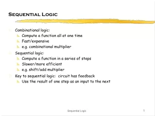
Sequential Circuits • Circuits with Feedback • Outputs = f(inputs, past inputs, past outputs) • Basis for building "memory" into logic circuits • Door combination lock is an example of a sequential circuit • State is memory • State is an "output" and an "input" to combinational logic • Combination storage elements are also memory value(4 bits) new equal reset Ld1 Ld2 Ld3 mux control C1 C2 C3 comb. logic multiplexer clock state comparator equal open/closed Reg: C1, C2, C3 need a clock to load value
Digital combination lock state diagram • States: 5 states • represent point in execution of machine • each state has outputs • Transitions: 6 from state to state, 5 self transitions, 1 global • changes of state occur when clock says its ok • based on value of inputs • Inputs: reset, new, results of comparisons • Output: open/closed ERR closed C1!=value& new C2!=value& new C3!=value& new S1 S2 S3 OPEN reset closed closed closed open C1==value& new C2==value& new C3==value& new not new i.e., no digits entered not new not new
Edge-Triggered Flip-Flops D’ D 0 R Q Clk=1 Q’ S 0 D’ D • Sensitive to inputs only near edge of clock signal (not while high) holds D' when clock goes low negative edge-triggered D flip-flop (D-FF) 4-5 gate delays must respect setup and hold time constraints to successfullycapture input holds D whenclock goes low characteristic equationQ(t+1) = D
D’ D’ D D D’ D’ R R Q Q Clk=0 Clk=0 S S D D D’ D’ D new D Edge-Triggered Flip-Flops (cont’d) • Step-by-step analysis new D old D when clock is low data is held when clock goes high-to-low data is latched
Edge-Triggered Flip-Flops (cont’d) • Positive edge-triggered • Inputs sampled on rising edge; outputs change after rising edge • Negative edge-triggered flip-flops • Inputs sampled on falling edge; outputs change after falling edge 100 D CLK Qpos Qpos' Qneg Qneg' positive edge-triggered FF negative edge-triggered FF
Timing Methodologies • Rules for interconnecting components and clocks • Guarantee proper operation of system when strictly followed • Approach depends on building blocks used for memory elements • Focus on systems with edge-triggered flip-flops • Found in programmable logic devices • Many custom integrated circuits focus on level-sensitive latches • Basic rules for correct timing: • (1) Correct inputs, with respect to time, are provided to the flip-flops • (2) No flip-flop changes state more than once per clocking event
D D Q Q Tsu Th input clock Timing Methodologies (cont’d) • Definition of terms • clock: periodic event, causes state of memory element to change; can be rising or falling edge, or high or low level • setup time: minimum time before the clocking event by which the input must be stable (Tsu) • hold time: minimum time after the clocking event until which the input must remain stable (Th) data clock there is a timing "window" around the clocking event during which the input must remain stable and unchanged in order to be recognized stable changing data clock
D Q D Q G Comparison of Latches and Flip-Flops D CLK Qedge Qlatch CLK positiveedge-triggeredflip-flop CLK transparent(level-sensitive)latch behavior is the same unless input changes while the clock is high
Tsu1.8ns Th0.5ns D Tsu1.8ns Th0.5ns CLK Tw 3.3ns Tplh3.6ns1.1ns Tphl3.6ns1.1ns Q Typical Timing Specifications • Positive edge-triggered D flip-flop • Setup and hold times • Minimum clock width • Propagation delays (low to high, high to low, max and typical) data from 374 posedge triggered flip flop all measurements are made from the clocking event that is, the rising edge of the clock
Q0 Q1 D D Q Q IN OUT CLK Cascading Edge-triggered Flip-Flops • Shift register • New value goes into first stage • While previous value of first stage goes into second stage • Consider setup/hold/propagation delays (prop must be > hold) 100 IN Q0 Q1 CLK
Cascading Edge-triggered Flip-Flops (cont’d) • Why this works • Propagation delays exceed hold times • Clock width constraint exceeds setup time • This guarantees following stage will latch current value before it changes to new value In Q0 Q1 CLK Tsu 4ns Tsu 4ns timing constraints guarantee proper operation of cascaded components Tp 3ns Tp 3ns assumes infinitely fast distribution of the clock Th 2ns Th 2ns
Clock Skew • The problem • Correct behavior assumes next state of all storage elementsdetermined by all storage elements at the same time • This is difficult in high-performance systems because time for clock to arrive at flip-flop is comparable to delays through logic • Effect of skew on cascaded flip-flops: 100 In Q0 Q1 CLK0 CLK1 CLK1 is a delayed version of CLK0 In our design we expect CLK1 and CLK0 arrive at the same time original state: IN = 0, Q0 = 1, Q1 = 1 due to skew, next state becomes: Q0 = 0, Q1 = 0, and not Q0 = 0, Q1 = 1
Summary of Latches and Flip-Flops • Development of D-FF • Level-sensitive used in custom integrated circuit • Edge-triggered used in programmable logic devices • Good choice for data storage register • Historically J-K FF was popular but now never used • Similar to R-S but with 1-1 being used to toggle output (complement state) • Good in old days of TTL/SSI (more complex input function: D = JQ' + K'Q • Not a good choice for PALs/PLAs as it requires 2 inputs • Can always be implemented using D-FF • Preset and clear inputs are highly desirable on flip-flops • Used at start-up or to reset system to a known state
Dealing with Synchronization Failure • Probability of failure can never be reduced to 0, but it can be reduced • (1) slow down the system clock: this gives the synchronizer more time to decay into a steady state; synchronizer failure becomes a big problem for very high speed systems • (2) use fastest possible logic technology in the synchronizer • (3) cascade two synchronizers: this effectively synchronizes twice (both would have to fail) Q asynchronous input synchronized input D Q D Clk synchronous system
D Q D Q D Q D Q D Q Handling Asynchronous Inputs • Never allow asynchronous inputs to fan-out to more than one flip-flop • Synchronize as soon as possible and then treat as synchronous signal Clocked Synchronizer Synchronous System Q0 Q0 Async Async Input Input Clock Clock Q1 Q1 Clock Clock
Handling Asynchronous Inputs (cont’d) • What can go wrong? • Input changes too close to clock edge (violating setup time constraint) In Q0 Q1 CLK In is asynchronous and fans out to D0 and D1one FF catches the signal, one does not inconsistent state may be reached!
OUT1 OUT2 OUT3 OUT4 "0" R S R S R S R S D Q D Q D Q D Q CLK IN1 IN2 IN3 IN4 Registers • Collections of flip-flops with similar controls and logic • Stored values somehow related (e.g., form binary value) • Share clock, reset, and set lines • Similar logic at each stage • Examples • Shift registers • Counters
OUT1 OUT2 OUT3 OUT4 D Q D Q D Q D Q IN CLK Shift Register • Holds samples of input • Store last 4 input values in sequence • 4-bit shift register:
output left_in right_out left_out right_in clear s0 clock s1 input Universal Shift Register • Holds 4 values • Serial or parallel inputs • Serial or parallel outputs • Permits shift left or right • Load new input clear sets the register contentsand output to 0s1 and s0 determine the shift function s0 s1 function 0 0 hold state 0 1 shift right 1 0 shift left 1 1 load new input
0 1 2 3 Design of Universal Shift Register • Consider one of the four flip-flops • New value at next clock cycle: Nth cell to N-1th cell to N+1th cell Q D CLK CLEAR clear s0 s1 new value 1 – – 0 0 0 0 output 0 0 1 output value of FF to left (shift right) 0 1 0 output value of FF to right (shift left) 0 1 1 input s0 and s1control mux Q[N-1](left) Q[N+1](right) Input[N]
OUT OUT1 OUT2 OUT3 OUT4 D Q D Q D Q D Q IN CLK Pattern Recognizer • Combinational function of input samples • In this case, recognizing the pattern 1001 on the single input signal
OUT1 OUT2 OUT3 OUT4 D Q D Q D Q D Q IN CLK OUT1 OUT2 OUT3 OUT4 D Q D Q D Q D Q IN CLK Counters • Sequences through a fixed set of patterns • In this case, 1000, 0100, 0010, 0001 • If one of the patterns is its initial state (by loading or set/reset) • Mobius (or Johnson) counter • In this case, 1000, 1100, 1110, 1111, 0111, 0011, 0001, 0000
OUT1 OUT2 OUT3 OUT4 D Q D Q D Q D Q CLK "1" Binary Counter • Logic between registers (not just multiplexer) • XOR decides when bit should be toggled • Always for low-order bit, only when first bit is true for second bit, and so on
"1" "0""1""1""0" EN DCBA LOAD CLK CLR RCO QDQCQBQA "0" "1" "0""0""0""0" EN DCBA LOAD CLK CLR RCO QDQCQBQA Offset Counters • Starting offset counters – use of synchronous load • e.g., 0110, 0111, 1000, 1001, 1010, 1011, 1100, 1101, 1111, 0110, . . . • Ending offset counter – comparator for ending value • e.g., 0000, 0001, 0010, ..., 1100, 1101, 0000 • Combinations of the above (start and stop value)
outputlogic Outputs Inputs next statelogic Next State Current State State Machine Model • Values stored in registers represent the state of the circuit • Combinational logic computes: • Next state • Function of current state and inputs • Outputs • Function of current state and inputs (Mealy machine) • Function of current state only (Moore machine)
outputlogic Outputs Inputs next statelogic Next State Next State State Current State 0 1 2 3 4 5 Clock State Machine Model (cont’d) • States: S1, S2, ..., Sk • Inputs: I1, I2, ..., Im • Outputs: O1, O2, ..., On • Transition function: Fs(Si, Ij) • Output function: Fo(Si) or Fo(Si, Ij)
logic foroutputs inputs inputs outputs combinational logic for next state combinational logic fornext state logic foroutputs reg reg outputs state feedback state feedback Comparison of Mealy and Moore Machines • Mealy Machines tend to have less states • Different outputs on arcs (n^2) rather than states (n) • Moore Machines are safer to use • Outputs change at clock edge (always one cycle later) • In Mealy machines, input change can cause output change as soon as logic is done – a big problem when two machines are interconnected – asynchronous feedback • Mealy Machines react faster to inputs • React in same cycle – don't need to wait for clock • In Moore machines, more logic may be necessary to decode state into outputs – more gate delays after
Example: Vending Machine • Release item after 15 cents are deposited • Single coin slot for dimes, nickels • No change Reset N VendingMachineFSM Open CoinSensor ReleaseMechanism D Clock
Reset S0 N D S1 S2 N D N D S3 S4 [open] S5 [open] S6 [open] N S7 [open] Example: Vending Machine (cont’d) • Suitable Abstract Representation • Tabulate typical input sequences: • 3 nickels • nickel, dime • dime, nickel • two dimes • Draw state diagram: • Inputs: N, D, reset • Output: open chute • Assumptions: • Assume N and D assertedfor one cycle • Each state has a self loopfor N = D = 0 (no coin)
present inputs next outputstate D N state open 0¢ 0 0 0¢ 0 0 1 5¢ 0 1 0 10¢ 0 1 1 – – 5¢ 0 0 5¢ 0 0 1 10¢ 0 1 0 15¢ 0 1 1 – –10¢ 0 0 10¢ 0 0 1 15¢ 0 1 0 15¢ 0 1 1 – –15¢ – – 15¢ 1 Reset 0¢ N 5¢ D N 10¢ D N + D 15¢ [open] symbolic state table Example: Vending Machine (cont’d) • Minimize number of states - reuse states whenever possible
Example: Vending Machine (cont’d) • Uniquely Encode States, binary encoding is selected present state inputs next state output Q1 Q0 D N D1 D0 open 0 0 0 0 0 0 0 0 1 0 1 0 1 0 1 0 0 1 1 – – – 0 1 0 0 0 1 0 0 1 1 0 0 1 0 1 1 0 1 1 – – – 1 0 0 0 1 0 0 0 1 1 1 0 1 0 1 1 0 1 1 – – – 1 1 – – 1 1 1
Q1 Q1 Q1 Open D1 D0 0 0 1 1 0 1 1 1 X X X X 1 1 1 1 0 0 1 0 0 0 1 0 X X X X 0 0 1 0 0 1 1 0 1 0 1 1 X X X X 0 1 1 1 N N N D D D Q0 Q0 Q0 Example: Vending Machine (cont’d) • Mapping to Logic D1 = Q1 + D + Q0 N D0 = Q0’ N + Q0 N’ + Q1 N + Q1 D OPEN = Q1 Q0
Example: Vending Machine (cont’d) • One-hot Encoding present state inputs next state outputQ3 Q2 Q1 Q0 D N D3 D2 D1 D0 open 0 0 0 1 0 0 0 0 0 1 0 0 1 0 0 1 0 0 1 0 0 1 0 0 0 1 1 - - - - - 0 0 1 0 0 0 0 0 1 0 0 0 1 0 1 0 0 0 1 0 1 0 0 0 0 1 1 - - - - - 0 1 0 0 0 0 0 1 0 0 0 0 1 1 0 0 0 0 1 0 1 0 0 0 0 1 1 - - - - - 1 0 0 0 - - 1 0 0 0 1 D0 = Q0 D’ N’ D1 = Q0 N + Q1 D’ N’ D2 = Q0 D + Q1 N + Q2 D’ N’ D3 = Q1 D + Q2 D + Q2 N + Q3 OPEN = Q3
N’ D’ + Reset (N’ D’ + Reset)/0 Reset Reset/0 0¢ [0] 0¢ N’ D’ N’ D’/0 N N/0 5¢ [0] 5¢ D D/0 N’ D’ N’ D’/0 N N/0 10¢ [0] 10¢ N’ D’ N’ D’/0 D D/1 N+D N+D/1 15¢ [1] 15¢ Reset’ Reset’/1 Equivalent Mealy and Moore State Diagrams Moore machine outputs associated with state • Mealy machine • outputs associated with transitions
Vending Machine (cont’d) • OPEN = Q1Q0 creates a combinational delay after Q1 and Q0 change • This can be corrected by retiming, i.e., move flip-flops and logic through each other to improve delay • OPEN = reset'(Q1 + D + Q0N)(Q0'N + Q0N' + Q1N + Q1D) = reset'(Q1Q0N' + Q1N + Q1D + Q0'ND + Q0N'D) • Implementation now looks like a synchronous Mealy machine • Common for programmable devices to have FF at end of logic
Finite State Machine Optimization • State Minimization • Fewer states require fewer state bits • Fewer bits require fewer logic equations • Encodings: State, Inputs, Outputs • State encoding with fewer bits has fewer equations to implement • However, each may be more complex • State encoding with more bits (e.g., one-hot) has simpler equations • Complexity directly related to complexity of state diagram • Input/output encoding may or may not be under designer control
Algorithmic Approach to State Minimization • Goal – identify and combine states that have equivalent behavior • Equivalent States: • Same output • For all input combinations, states transition to same or equivalent states • Algorithm Sketch • 1. Place all states in one set • 2. Initially partition set based on output behavior • 3. Successively partition resulting subsets based on next state transitions • 4. Repeat (3) until no further partitioning is required • states left in the same set are equivalent • Polynomial time procedure
Input Next State Output Sequence Present State X=0 X=1 X=0 X=1 Reset S0 S1 S2 0 0 0 S1 S3 S4 0 0 1 S2 S5 S6 0 0 00 S3 S0 S0 0 0 01 S4 S0 S0 1 0 10 S5 S0 S0 0 0 11 S6 S0 S0 1 0 S0 0/0 1/0 S1 S2 0/0 1/0 0/0 1/0 S3 S4 S5 S6 1/0 1/0 1/0 1/0 0/0 0/1 0/0 0/1 State Minimization Example • Sequence Detector for 010 or 110
Input Next State Output Sequence Present State X=0 X=1 X=0 X=1 Reset S0 S1 S2 0 0 0 S1 S3 S4 0 0 1 S2 S5 S6 0 0 00 S3 S0 S0 0 0 01 S4 S0 S0 1 0 10 S5 S0 S0 0 0 11 S6 S0 S0 1 0 Method of Successive Partitions ( S0 S1 S2 S3 S4 S5 S6 ) ( S0 S1 S2 S3 S5 ) ( S4 S6 ) ( S0 S3 S5 ) ( S1 S2 ) ( S4 S6 ) ( S0 ) ( S3 S5 ) ( S1 S2 ) ( S4 S6 ) S1 is equivalent to S2 S3 is equivalent to S5 S4 is equivalent to S6
Input Next State Output Sequence Present State X=0 X=1 X=0 X=1 Reset S0 S1' S1' 0 0 0 + 1 S1' S3' S4' 0 0 X0 S3' S0 S0 0 0 X1 S4' S0 S0 1 0 S0 X/0 S1’ 0/0 1/0 S4’ S3’ X/0 0/1 1/0 Minimized FSM • State minimized sequence detector for 010 or 110
00 10 S0[1] S1 [0] 00 01 10 11 present next state output state 00 01 10 11 S0 S0 S1 S2 S3 1 S1 S0 S3 S1 S4 0 S2 S1 S3 S2 S4 1 S3 S1 S0 S4 S5 0 S4 S0 S1 S2 S5 1 S5 S1 S4 S0 S5 0 11 01 00 01 00 S2[1] S3 [0] 01 10 10 11 11 01 10 10 S4[1] S5 [0] 11 00 00 01 11 More Complex State Minimization • Multiple input example inputs here symbolic state transition table
present next state output state 00 01 10 11 S0' S0' S1 S2 S3' 1 S1 S0' S3' S1 S3' 0 S2 S1 S3' S2 S0' 1 S3' S1 S0' S0' S3' 0 S1 S0-S1 S1-S3 S2 S2-S2 S3-S4 S0-S1 S3-S0 S3 S1-S4 minimized state table (S0==S4) (S3==S5) S4-S5 S0-S0 S1-S0 S1-S1 S3-S1 S4 S2-S2 S2-S2 S3-S5 S4-S5 S0-S1 S1-S1 S3-S4 S0-S4 S5 S1-S0 S4-S0 S4-S5 S5-S5 S0 S1 S2 S3 S4 Minimized FSM • Implication Chart Method • Cross out incompatible states based on outputs • Then cross out more cells if indexed chart entries are already crossed out
State Assignment Strategies • Possible Strategies • Sequential – just number states as they appear in the state table • Random – pick random codes • One-hot – use as many state bits as there are states (bit=1 –> state) • Output – use outputs to help encode states • Heuristic – rules of thumb that seem to work in most cases • No guarantee of optimality – another intractable problem
One-hot State Assignment • Simple • Easy to encode, debug • Small Logic Functions • Each state function requires only predecessor state bits as input • Good for Programmable Devices • Lots of flip-flops readily available • Simple functions with small support (signals its dependent upon) • Impractical for Large Machines • Too many states require too many flip-flops • Decompose FSMs into smaller pieces that can be one-hot encoded • Many Slight Variations to One-hot • One-hot + all-0
a b i / j i / k c a i / j k / l b c a c i / j i / j b d Heuristics for State Assignment • Adjacent codes to states that share a common next state • Group 1's in next state map • Adjacent codes to states that share a common ancestor state • Group 1's in next state map • Adjacent codes to states that have a common output behavior • Group 1's in output map I Q Q+ Oi a c ji b c k c = i * a+ i * b I Q Q+ Oi a b jk a c l b = i * ac = k * a I Q Q+ Oi a b ji c d j j = i * a + i * cb = i * ad = i * c
Output-Based Encoding • Reuse outputs as state bits - use outputs to help distinguish states • Why create new functions for state bits when output can serve as well • Fits in nicely with synchronous Mealy implementations
Current State Assignment Approaches • For tight encodings using close to the minimum number of state bits • Heuristic approaches are not even close to optimality • Used in custom chip design • One-hot encoding • Easy for small state machines • Generates small equations with easy to estimate complexity • Common in FPGAs and other programmable logic • Output-based encoding • Ad hoc - no tools • Most common approach taken by human designers • Yields very small circuits for most FSMs