Download
1 / 14
140 likes | 154 Vues
This update discusses the progress made in testing and characterizing the LSC scheme, developing DC readout schemes, testing QND techniques, and extrapolating to AdLIGO via simulation. The update also covers the objectives, recent work, and results in achieving lock acquisition for the DRSE interferometer and implementing the electronics for PD MMT1 OMC Tip/Tilt RF PICKOFF.

E N D
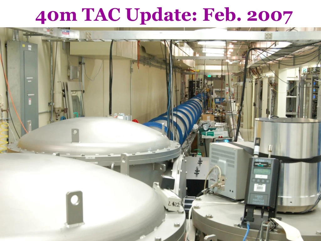
40m TAC Update: Feb. 2007 G070016-00-R
Test/Characterize LSC scheme • Develop DC readout scheme • Characterize noise mechanisms • Test QND techniques • Develop/Test ASC scheme • Extrapolate to AdLIGO via simulation • Objectives: • Develop lock acquisition procedure of DRSE interferometer, as close as possible to aLIGO optical design ELECTRONICS PD MMT1 OMC Tip/Tilt RF PICKOFF Prototyping will yield crucial information about how to build and run eLIGO & aLIGO MMT2 Squeezer Pickoff G070016-00-R
Work since last update (Oct. 06) • PR FPMI Locking • Another Vent for clipping/squeezing • Automation/scripting • Modeling G070016-00-R
Mode matching telescope OMC DC PD DC readout beamline From SRM G070016-00-R
DC Readout components • Two in-vac PZT tip-tilt steering mirrors (bad Piezo-Jena) • SOS-like tip/tilt ‘undulators’ to be used for eLIGO/aLIGO. Development by ANU. • MMT for OMC (pico-controlled). • Pico signal breaks locks via large EMI from drive signal. • Output Mode cleaner • Roughly similar to eLIGO design • eLIGO to use more of a LISA-like design • In-Vacuum Photodetector • 2mm InGaAs diodes, with an amplifier/whitening circuit in a can. • eLIGO to have similar circuit (so far) • PCIX system for digital control • digital lock-in software for controlling 5 DOFs • “oscillator” generated digitally, all-digital dither-lock-in module • Interfaces to existing RFM network • 32 kHz real time control G070016-00-R
DC READOUT COMMISIONING • most hardware installed, tested • Need rework of the DC PD readout to get above ADC noise • All software installed, “tested” • PCIX, Myrinet-RFM, multi-framebuilders, multi-AWG • Real shakedown of new/old digital handoffs not done yet; part of the noise hunting. • Simulink generation of FE code (BorkSpace) • Auto EPICS generation (screens, dbs, etc.) • OMCL dither locked (dither freq 12kHz, UGF 100Hz) • OMC ASC dither locked (two tip/tilts, 4 DOFs) • dither freqs ~4,5,6,7 kHz • UGFs 2@20Hz, 2@subHz G070016-00-R
OMC mode scan(not yet mode matched!) carrier TEM00 carrier02,11,20 33 MHz TEM00 33 MHz TEM00 carrier01,10 carrier n+m=4 carrier n+m=3 33 MHz02,11,20 G070016-00-R
Lock Acquisition Schemes Three lock acquisition schemes are currently pursued: • ‘Smooth’ PRFPMI: early stages. • Initially lock using DC signals for ARMs and MICH with large offsets. • Transition to CARM/DARM, but with large offset for MICH to minimize arm coupling until we feedback CARM wideband. • Then reduce MICH offset. • ‘Bang’ PRFPMI: works, needs tuning • DRSE. • Needs more work on the initial acquisition. G070016-00-R
Lock Acquisition and Optickle Modeling • When developing lock acquisition schemes we use Optickle to; • Find error signals to navigate locking space. • Check error signal sign and amplitude whilst various parameters are varied. e.g. For Bang PRFPMI, we check the phase differences for a CARM handoff from SPOB_DC to POXI. It can be seen that there is a phase difference around the MCL - MCF crossover. G070016-00-R
DC Readout DARM noise • PRFPMI (like iLIGO) • SRM mis-aligned • DARM offset: ~ 15 pm • Control Scheme • DARM: OMC Transmission • MICH: REFL_Q • PRC: REFL_I • Com Mode: POY_I • UP NEXT: • Noise characterization G070016-00-R
Flipper inserted between SRM and OMC The squeezed vacuum is injected into the dark port via the optical circulator (Faraday isolator and PBS). Noise-locking technique is used to lock the squeeze angle so that broadband reduction of the IFO shot noise can be achieved. Squeezing Work Goal:Demonstration of a Squeezing-Enhanced Interferometer Sensitivity • DRMI/RSE Quantum Noise Budget • Input Power to BS = 700mW • Homodyne Angle = 0 • Squeeze Angle = π/2 • Initial Squeezing Level = 5dB • Injection Loss = 10% • Detection Loss = 10% Modeled Improvement G070016-00-R
Generation of Squeezed Vacuum in Optical Parametric Oscillation and Injection of Squeezing to the IFO • The OPO is a 2.2cm long cavity composed of a periodically poled KTP crystal with flat/flat AR/AR surfaces and two coupling mirrors (R = 99.95% at 1064/532nm and R = 92%/4% at 1064/532nm). • The OPO is pumped by 300 mW of second-harmonic light at 532nm. • Quasi-phase matching is used and both the seed and pump are polarized in the same direction. • Frequency-shifted, orthogonally polarized light is used to lock the OPO cavity so that a vacuum field at 1064nm can couple to the cavity and get squeezed by its nonlinear interaction with the pump field in a TEM00 mode. • The picomotor mirror can be inserted in or out for squeezing-enhanced IFO measurements. • Isolation of a GW signal from the injection of squeezing is done by Faraday isolation. • The squeezing-enhanced GW-signal/shot-noise ratio is measured by the DC PD with high quantum efficiency (93%). PPKTP Coupling Mirrors G070016-00-R
Some Results & Future Work • About 6dB of scanned squeezing • About 4dB of phase-locked squeezing • Measured by the squeezing monitoring homodyne detector • Ready to be injected into the IFO in the next few weeks to demonstrate squeezing-enhanced IFO • Shot noise • Squeezed shot noise G070016-00-R