Download
1 / 32
320 likes | 335 Vues
Explore the motivation, techniques, and results of aggressive crunching for reducing the size of RC netlists generated by circuit extractors.

E N D
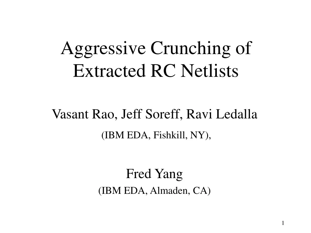
Aggressive Crunching of Extracted RC Netlists Vasant Rao, Jeff Soreff, Ravi Ledalla (IBM EDA, Fishkill, NY), Fred Yang (IBM EDA, Almaden, CA)
Agenda • Motivation for RC Crunching • Internal Node Elimination (TICER) • Resistor Short/Update (TICER+) • Examples • Results
Motivation for RC Crunching • Netlists generated by Circuit Extractors have far too many resistors which slow down Circuit Simulation significantly • Size of the netlist is huge • Large Circuit Matrices • Wide range of dynamic time-constants • due to wide range of resistor values • causes time-step control problems
RC Crunching Goals • Crunch Extracted RC netlist down significantly • reduce size (number of nodes/resistors) • preserve sparsity • preserve total capacitance • give user a size vs accuracy control knob • size of crunched network should vary inversely with error user is willing to tolerate. • If user does not care for accuracy, the crunched network should be a single node with no resistors. • Should have potential for Complete Crunching
g23 3 2 3 2 g2 g3 g34 g13 g12 g24 N g1 g4 4 1 4 1 g14 C C3 C2 C4 C1 Internal Node Elimination (TICER) TICER: B. N. Sheehan, ICCAD-1999 Conductance: Eliminate Node N With Capacitance C Merge parallel resistors & capacitors
Equilibrium Time Constant User Defined Threshold TICER Properties • Eliminates only internal (not source/sink) node. • Preserves Elmore Delay. • Handles Coupling Capacitors • TICER eliminates internal nodes with: • After elimination of a node of degree k: • Node count reduces by 1. • Resistors increase by fill-in count = • Restrict to preserve sparsity #Old R’s among neighbors #Deleted R’s #New R’s among neighbors
Resistor Short/Update (TICER+) • TICER does not eliminate sources/sinks. • Fill-in count restriction to preserve sparsity conflicts with complete crunching goal. • TICER+ consists of: • First run TICER with threshold t and fill-in limit a • Recommend a = 0. • Then short certain resistors and (possibly) update values of neighboring resistors • Work with Elmore delay (satisfies additive relations) • Limit accumulated delay error < t/10.
Notation: Delay from Root to Node Xbefore Shorting R Delay from Root to Node Xafter Shorting R Cumulative Down-stream Capacitance at X. K RK J I RI A B RJ Root R • First consider RC-Tree: Additive Relations
K RK+dK J RI+dI I RJ+dJ Root AB • After shorting R between A and B:
Optimization Problem Optimal Solution: Perturb resistors to minimize error due to shorting resistor R: • Update ONLY neighbors RJ of R connected to B: • This results in • Note: • Cannot preserve Elmore Delays at each sink • Delay error occurs at the merged node only • No error for sinks at A. Only error for sink at B. • All perturbations are positive - good. No Update Needed if B is a leaf Coupling Capacitors Handled
Overall TICER+ Crunching Algorithm 1. Run TICER with user-defined t and a a. First only internal nodes with degree 1 or 2. b. Then restrict to fill-in count of a. 2. Find Minimum (Resistive) Spanning Tree 3. Pick leafR with smallest 4. Short R and accumulate Error at merged node. 5. Check if total accumulated Error is 6. Repeat step 3 until above check fails. No update needed since R is a leaf
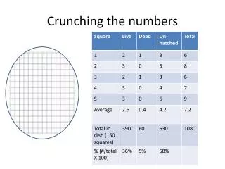
A B C D S E F G H I Example1 RC-Tree after TICER with a = 0 1 source S 9 sinks A-I Sink Cap = 10fF Internal Pin Cap = 1fF All R’s = 1W User sets t = 1ps Initially delay error e=0 at all nodes. 0 0 10fF 1W 0 Cannot Eliminate any Internal Node 0 0 0 0 0 0 0 14 nodes 13 resistors 0 0 0
After 1 short B 0 0 C A 0 D 10fs 0 0 0 S E 0 F 0 0 G 0 H 0 I
After 3 shorts ABC 0 D 10fs 0 0 0 S E 0 F 0 0 G 0 H 0 I
After 9 shorts ABC 31fF 10fs 1W DEF 0 S 10fs GHI 10fs
After 10 shorts DEF 41fs S ABC 10fs GHI 10fs
After 12 shorts Final Network: 2 nodes 1 resistor 41fs 1W ABCDEFGHI S Cap = 94fF Maximum delay error is 41fs < t /10 = 100fs. Further shorting will result in a delay error = 41 + 1.0*94 = 135fs > t /10 = 100fs
Example2 64 33 29 61 27 60 30 37 User sets: t = 8ps a = 0 35 55 58 41 54 43 38 52 53 46 48 59 44 47 24 45 18 22 28 36 21 11 16 8 3 15 4 6 2 1 14 13 9 12 23 20 10 5 17 7 19 50 42 49 51 25 39 34 65 resistors 64 nodes 2 loops 40 56 26 32 31 57 63 62
64 33 29 61 27 60 30 37 35 55 58 41 54 43 38 52 53 46 48 59 44 47 24 45 18 22 28 36 21 11 16 8 3 15 4 6 2 1 14 13 9 12 23 20 10 5 17 7 19 50 42 49 51 25 39 34 40 56 26 32 31 57 63 62
64 33 29 61 27 60 30 37 35 55 58 41 54 43 38 52 53 46 48 59 44 47 24 45 18 22 28 36 21 11 16 8 3 15 4 6 2 1 14 13 23 20 19 50 42 49 51 25 39 34 57 resistors 58 nodes 0 loops 40 56 26 32 31 57 63 62
64 33 29 61 27 60 30 37 35 55 58 41 54 43 38 52 53 46 48 59 44 47 24 45 18 22 28 36 21 11 16 8 3 15 4 6 2 1 14 13 23 20 19 50 42 49 51 25 39 34 40 56 26 32 31 57 63 62
Done with internal nodes with 2 or less resistive neighbors. 37 35 55 58 41 54 38 52 53 46 48 44 47 45 18 36 16 8 15 14 13 No loops!!! Now work on internal nodes with 3 or more resistive neighbors. 19 50 49 51 25 39 34 30 resistors 31 nodes 0 loops 40 56 57
37 35 55 58 41 54 38 52 53 46 48 44 47 45 18 36 16 8 14 13 Loop Formed 19 50 49 51 25 39 34 40 56 57
Internal Node Elimination (TICER) phase completed. Further elimination will increase resistor count (cause fill-ins) 37 35 55 41 58 54 38 53 46 48 44 18 36 16 14 19 50 25 30 resistors 23 nodes 39 34 40 56 57
Begin Resistor Short/Update Phase: Find Minimum Resistor Spanning Tree and select Root 37 35 55 41 58 54 38 53 46 48 44 Root 18 36 16 14 19 50 25 30 resistors 23 nodes 8 links 0.66ps 39 34 40 56 57 t/10 = 0.8ps
0.73ps 0.22ps 0.22ps 0.66ps 37 35 55 0.66ps 41 58 0.62ps 54 38 53 46 48 0.22ps 0.22ps 44 Root 18 0.67ps 36 16 34 0.66ps 19 50 25 28 resistors 22 nodes 7 links 39 40 56 0.67ps 57 0.67ps 0.22ps 0.22ps
0.73ps 57 0.66ps 0.66ps 54 55 Root 0.67ps 53 18 34 58 0.66ps 19 25 11 resistors 9 nodes 3 links 0.67ps
0.73ps 57 0.66ps +0.02ps 0.66ps 54 55 Root 0.67ps +0.13ps 53 18 34 58 0.66ps 19 25 11 resistors 9 nodes 3 links 0.67ps
0.73ps 57 End of Shorting Phase: Final RC Network after Crunching - Note that resistor update formula not used. 0.68ps Root 55 18 53 0.8ps 58 Any further shorting will violate 0.8ps delay error bound 0.67ps 5 resistors 5 nodes 1 link
d RC Results • TICER+ implemented in Transistor-level Static Timing Analyser (EinsTLT) used by IBM in production. • EinsTLT uses a fast simulator (ACES) • TICER+ performance measured by run-time savings in EinsTLT • TICER+ accuracy measured by sink-to-sinkstage-delay (d) difference (D): • computed by EinsTLT/ACES • NOT Elmore Delay
a Recommended Thresholds Threshold of TICER+ controls Run-Time vs Accuracy of EinsTLT 0 No Crunching 1.0ns Complete Crunching
Just TICER by itself is not good enough: • Size saturates too soon at fixed fill-in number • Increasing fill-in number: increases resistors significantly reduces nodes slightly