Download
1 / 42
500 likes | 993 Vues
PH 0101 UNIT-3 LECT - 5. Free Electron Laser, X-ray Free Electron Laser, Applications of Laser Holography. FREE ELECTRON LASER : Introduction :

E N D
PH 0101 UNIT-3 LECT - 5 • Free Electron Laser, • X-ray Free Electron Laser, • Applications of Laser • Holography UNIT III Lecture 5
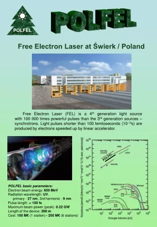
FREE ELECTRON LASER : Introduction : Free electron laser, or FEL, is a laser invented and developed by J.M.J. Madey in 1971. It is a powerful and challenging combination of particle-accelerator and laser physics . FEL is a relativistic electron tube that made use of the open optical resonator, that shares the same optical properties as conventional lasers such as emitting a beam consisting of coherentelectromagneticradiation which can reach high power, but which uses some very different operating principles to form the beam. UNIT III Lecture 5
Gas, liquid, or solid-state lasers such as diode lasers, which rely on bound atomic or molecular states, FELs use a relativisticelectron beam as the lasing medium, hence the term free electron. This gives them the widest frequency range of any laser type, and makes many of them widely tunable, currently ranging in wavelength from microwaves, through terahertz radiation and infrared, to the visible spectrum, to ultraviolet, to soft X-rays. UNIT III Lecture 5
BEAM CREATION : FREE ELECTRON LASER DIAGRAM UNIT III Lecture 5
A FEL can be created by a beam of electrons is accelerated to relativistic speeds. The beam passes through a periodic, transverse magnetic field. This field is produced by arranging magnets with alternating poles along the beam path. This array of magnets is sometimes called an undulator, or a "wiggler", because it forces the electrons in the beam to assume a sinusoidal path. The acceleration of the electrons along this path results in the release of a photon . Viewed relativistically in the rest frame of the electron, the magnetic field can be treated as if it were a virtual photon. The collision of the electron with this virtual photon creates an actual photon (Compton scattering). UNIT III Lecture 5
Contd. Mirrors capture the released photons to generate resonant gain. Adjusting either the beam energy (speed/energy of the electrons) or the field strength tunes the wavelength easily and rapidly over a wide range. Because Compton scattering is complicated in itself, it is easier to say that the electrons are forced onto a sinus path by the undulator and then switch in a rest frame moving along the undulator, where the electrons are oscillating, but not moving otherwise, and emit dipole radiation, and than switch back into the rest frame of the undulator to see that this dipole radiation is transformed into a forward emitted radiation of shorter wavelength. UNIT III Lecture 5
Contd. The photons emitted are related to the electron beam and magnetic field strength, an FEL can be tuned, i.e. the frequency or color can be controlled. Laser is that the electron motion is in phase (coherent) with the field of the light already emitted, so that the fields add coherently. The intensity of light depends on the square of the field, this increases the light output. Moving along the undulator any radiation will still move with the speed of light and pass over the electrons and lets them communicate to get in synchronization. UNIT III Lecture 5
Contd. Often same light (that is radiation) is introduced from the outside. Depending on the position along the undulator the oscillation of an electrons is in phase or not in phase with this radiation. The light either tries to accelerate or decelerate these electrons. It thereby gains or loses kinetic energy, so it moves faster or slower along the undulator. This causes the electrons to form bunches. They are synchronized, and will in turn emit synchronized (that is coherent) radiation. UNIT III Lecture 5
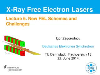
X-RAY FREE-ELECTRON LASERS : A free-electron laser that emits X-rays with a wavelength of the size of an atom (about 1 Å) can be built because of a favorable and interesting phenomenon of self-organization of the electrons in a relativistic beam, known as the free-electron laser collective instability. This instability takes an electron beam with a random electron position distribution, and changes it into a distribution with electrons regularly spaced at about the x-ray wavelength, producing what could be called a 1-dimensional electron crystal. The radiation from this crystal has the new and exciting properties UNIT III Lecture 5
MEDICAL APPLICATIONS : It was reported that at infrared wavelengths, water in tissue was heated by the laser, but at 915, 1210 and 1720 nm, subsurface lipids were differentially heated more strongly than water. The possible applications include the selective destruction of sebum lipids to treat acne, as well as targeting other lipids for the treatment of cellulite and atherosclerosis. MILITARY APPLICATIONS : FEL is also considered by as a good candidate for anti-missile directed-energy weapon. Significant progress is being made in increasing FEL power levels (already at 10 kW) and it should be possible to build compact multi-megawatt class FEL lasers (Airborne megawatt class free-electron laser for defense and security UNIT III Lecture 5
IN INDUSTRY Drilling : Laser drilling using either single or multiple pulses from a stationary laser beam produces Holes. This technique is often called as laser percussion hole drilling. In percussion drilling the work piece is placed at or near the focal point of the laser beam. Short pulses from the laser causes a small volume of work piece material to be first illuminated, then partially melted and partially vaporized. The explosive escape of the work piece material causes most of the volume of molten material to be removed as a spray of droplets. Any material can be drilled with hole size ranging from 0.1 mm to 1.2 mm with length to diameter ratio 100:1. UNIT III Lecture 5
CUTTING : • Holes with diameters larger than 1.2 mm (approx.) cannot be produced by laser percussion drilling because of lack of power density in defocused beam. • Hole sizes larger than 0.5 mm are usually laser cut rather than drilled because the percussion-drilled holes have the characteristic rough shape that lacks the high degree of roundness. UNIT III Lecture 5
Countd. • The process of laser cutting combines the concentrated light from the laser with a high velocity gas jet to either vapourise (non-metals) or to melt (metals) and thus rapidly remove material. • Cutting is accomplished without generating any cutting forces at high speeds. • Laser cutting of a workpiece can be started at any location and can be continued in any direction. UNIT III Lecture 5
MARKING : • A pulsed laser with high peak power density in conjunction with computer-controlled beam scanning system is generally used in laser marking. • As the beam is scanned across the work piece, it vaporizes a series of overlapping blind holes to produce smooth bottomed grooves that make up the identification letters and symbols. T • hese grooves are 0.25 mm wide and can be of any depth up to approximately 0.25 mm. • Uniformity of groove depth is maintained up to an accuracy of usually 0.005 mm. UNIT III Lecture 5
To ensure that material is removed completely and to minimize thermal damage to the work piece, a special method of pulsing a laser beam is often used with laser markers. • With such pulsed lasers (lasting only a few nanoseconds) power densities adequate to cause sublimation of work materials are easily attained. • It is this combination of high power density and short pulse duration that account for the laser’s unique ability to smoothly machine blind features in metals. UNIT III Lecture 5
WELDING : • For low distortion, high speed and autogenous welds lasers are used. • Both spot and seam welding can be performed either through pulsed lasers or continuous wave lasers. For seam welding pulsed lasers capable of high repetition rates or CO2 lasers are suitable. • Parts to be welded must have a tight fit with gap of less than 5% the thickness of the material. • Argon and helium gas is used to locally protect the weld puddle from oxidation. UNIT III Lecture 5
Countd. • One important application of laser welding involves sealing of electronic packages in special atmospheres. • The operation is performed inside a chamber containing the special atmosphere, thus the packaging contains the special atmosphere. HEAT TREATMENT : • Lasers are generally used for surface hardening of steels (carbon percentage greater than 0.3) upto 2 mm depth. • Laser beam is defocused to produce a power density of only 150 to 1500 W/cm2 causing heating of the part surface. UNIT III Lecture 5
Contd. • The beam is traversed across the work surface at a rate fast enough to avoid surface melting, heating rate up to 2,00,000C/s are obtained on the surface. • The heat is conducted from the surface into a thin finite volume of the metal beneath the beam. • This volume of metal is rapidly heated beyond its upper critical temperature, transforming it to Austenite. • As the beam passes, a steady state condition between heat input and heat conduction will be reached lasting from 0.01 to 0.6 second. • When the beam has moved on, self-quenching of the heated layer occur because of the rapid flow of heat into the cool substrate. UNIT III Lecture 5
Countd. • Carbon dioxide lasers are most often used for surface hardening because of their cost effectiveness. • These lasers emit the far infrared portion of the spectrum at a wavelength of 10.6 microns which is highly reflective on a bare metal surface. • To maximise laser beam absorption, surfaces must be coated with an absorptive material. Typical coatings include flat black paint, colloidal graphite or black oxide. UNIT III Lecture 5
CLADDING : • In this process alloys are melt and selectively deposited onto part surface. • Defocused laser beam and a local shield gas are used to melt the alloy. • By using the laser to rapidly fuse powder, wire or inplant inserts into a surface, distortion of the part and dilution of the cladding material can be made a minimum. • The application of laser cladding include deposition of wear resisting layers on valve seaks piston, rings, rock drills, and turbine blades. UNIT III Lecture 5
IN MEDICINE : Photodynamic therapy (PDT) : • Certain chemical agents exist which have a particularly specific affinity for malignant cells. When administered systematically, they preferentially concentrate on the cancer cells. • Here they act as sensitizing agents, i.e., they make the cancer cells more susceptible to destruction from external energy stimulus than unsensitized cells. • Current models of PDT laser units employ a 20 W argon tuneable dye laser, producing a red light of 630 nm, capable of penetrating tissues to a depth of 1.5 to 2 cm. UNIT III Lecture 5
Antibacterial uses : • Russian workers have used special low-energy near infrared lasers with a wavelength of 890 nm for eradication of infections, all laser actions on the organisms occurred through the skin only, providing a non-invasive method of treating such infections. • More significant work has been done in infective conditions of the teeth, specifically the root canal dentin and periodontal pockets, where infections are particularly difficult to eradicate. UNIT III Lecture 5
Dentistry “Millenium” laser device : Biolase Inc., California, USA has developed a laser which employs jet of laser-powered water to cut teeth and repair cavities painlessly. Gastric tumours : • Cancer of the gastric cardia producing dysphagia is amenable to laser therapy. • Small gastric tumors and early gastric cancers can be treated by endoscopic Nd:YAG laser irradiation. • Oesophageal and gastric outlet strictures can be opened up by incision with laser. UNIT III Lecture 5
Ophthalmology : • The argon laser is used in diabetic retinopathy, retinal tears and miscellaneous retinopathesis. Gastroenterology : • Laser treatment of gastrointestinal disorders is still fairly limited, even though considerable advances have been made in gastrointestinal endoscopes. • Endoscope is the only way by which a laser energy may be delivered to an internal target lesion. • Argon laser, Nd:YAG laser and diode lasers can be passed along flexible quartz fibers. • These are known as fiber optic lasers. UNIT III Lecture 5
Countd. • The quartz fiber with the laser beam running through it is passed through the endoscope’s biopsy channel, a tube is placed around the fiber through which CO2 gas is blown, both to clear blood from the end of the fiber and off the target site. • The CO2 is usually vented by a narrow-bore nasogastric tube. • Laser management of certain lesions, e.g., bleeding ulcer, is facilitated by the no-touch property of the laser, whereby it can exert its effect without coming in direct contact with the target. UNIT III Lecture 5
IN COMMUNICATION : • Communication by laser is attractive for several reasons. • First is the extreme directionality of laser beams compared to the beams produced by typical microwave antennas. • Another reason that optical communication attractive is the information carrying potential of laser beams. • The amount of information that can be sent over an electromagnetic wave is proportional to the bandwidth of the wave. UNIT III Lecture 5
Countd. • A specialized application that has received a significant attention is the use of lasers in space communications, where atmospheric interference is not a problem, the distances are enormous, and the data rates and system weight are more significant than the cost of individual components. • A second application is that of a rapidly installed, terrestrial communications link for short distances, as between adjacent office building in a city. UNIT III Lecture 5
HOLOGRAPHY Definition : The technique of recording of the complete information of an object (ie, its amplitude and phase) is called Holography (Holo – whole; graphy – recording). UNIT III Lecture 5
Comparison between holography and photography UNIT III Lecture 5
RECORDING PROCESS UNIT III Lecture 5
Recording Technique – Construction of a Hologram : • A monochromatic laser beam from the source is made to fall on beam splitter. • Beam splitter splits the incident beam into two. • One beam is made to fall on silver coated mirror M1 and after reflection, it is directed towards the photographic plate – reference wave. • Another beam is made to scatter by the object – object wave. • The reference wave and object wave interfere and the interference pattern is recorded on a high resolution photographic plate • The developed photographic plate is known as hologram UNIT III Lecture 5
Reconstruction Process : • The hologram is illuminated by the reference wave • Holography is a phenomenon of wave front reconstruction • To the observer the reconstructed wavefront appears to be coming from the object itself and a virtual image is seen. UNIT III Lecture 5
RECONSTRUCTION PROCESS UNIT III Lecture 5
APPLICATIONS OF HOLOGRAPHY : 1. Holographic interferometry : • Double exposure holographic interferometry: Measurement of small displacements or distortions of an object. • Real time holographic interferometry: Measurement of strains of object as they actually deform. • Time-average holographic interferometry: Examination of spatial characteristics of low amplitude vibrations of an object. 2. Holographic computer memories : High density optical storage UNIT III Lecture 5
Holograohic mass storage : • An intriguing approach for next generation data–storage uses optical holography to store information throughout the three–dimensional volume of a material. • By superimposing many holograms within the same volume of the recording medium, holograms can potentially store data at a volumetric density of one bit per cubic wavelength. • Given a typical laser wavelength of 500 nm or so, this density corresponds to 1012 bits (1 Terabit) per cubic centimeter or more. • In holographic storage, data are transferred to and from the storage material as 2–D images composed of thousands of pixels, each of which represents a single bit of information. UNIT III Lecture 5
Contd. • Since an entire “page of data” can be retrieved by a photodetector at the same time, rather than bit–by–bit, the holographic scheme promises fast readout rates as well as high density. • If a thousand holograms, each containing a million pixels, could be retrieved every second, for instance, then the output data rate would reach 1 Gigabit per second. (For comparison, a DVD optical–disk player reads data 100 times slower.) • To use volume holography as a storage technology, digital data must be imprinted onto the object beam for recording and then retrieved from the reconstructed object beam during readout. UNIT III Lecture 5
Holograghic data storage UNIT III Lecture 5
Data are imprinted onto the object beam by shining the light through a pixelated device called a spatial light modulator. • The reference beam overlaps with the object beam on the storage material, where the interference pattern is stored as a change in absorption, refractive index or thickness of the medium. • A pair of lenses image the data through the storage material onto a pixelated detector array, such as a charge coupled device (CCD). UNIT III Lecture 5
Contd. • To maximize the storage density, the hologram is usually recorded where the object beam is tightly focused • correct reference beam must first be directed to the appropriate spot within the storage media. • The hologram is then reconstructed by the reference beam, and a weak copy of the original object beam continues along the imaging path to the camera, where the optical output is detected and converted to digital data UNIT III Lecture 5
Contd. • The speed of a storage device can be jointly described by two parameters: the readout rate (in bits per second) and the latency, or time delay between asking for and receiving a particular bit of data. • The latency tends to be dominated by mechanical movement, especially if the storage media has to be moved. • The readout rate is often dictated by the camera integration time: the reference beam reconstructs a hologram until a sufficient number of photons accumulate to differentiate bright and dark pixels. • A frequently mentioned goal is an integration time of about 1 millisecond, which implies that 1000 pages of data can be retrieved per second. UNIT III Lecture 5
Contd. • Materials for writing permanent volume holograms generally involve irreversible photochemical reactions that are triggered by the bright regions of the optical interference pattern. • A photopolymer material, for example, polymerizes in response to optical illumination: material diffuses from darker to brighter regions so that short monomer chains can bind together to form long molecular chains. • And in a so-called direct-write or photochromic material, the illuminated molecules undergo a local change in their absorption or index of refraction, which is driven by photochemistry or photo-induced molecular reconfiguration. UNIT III Lecture 5
Contd. • Most erasable holographic materials are inorganic photorefractive crystals doped with transition metals or rare-earth ions. • These crystals are often available in centimetre-thick samples and include lithium niobate, strontium barium niobate and barium titanate doped with iron, cerium, praseodymium or manganese. • These materials react to the light and dark regions of an interference pattern by transporting and trapping electrons, which subsequently leads to a local change in the index of refraction. • The trapped charge can be rearranged by later illumination, so it is possible to erase recorded holograms and replace them with new ones. UNIT III Lecture 5