Download
1 / 30
320 likes | 572 Vues
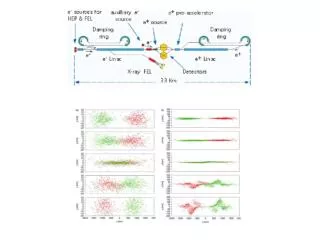
X-ray Free Electron Laser (FEL) Beamline Challenges. Philip Heimann (SLAC) Armin Busse, Yiping Feng, Joe Frisch, Nicholas Kelez, Jacek Krzywinski, Stefan Moeller, Michael Rowen, Peter Stefan and Jim Welch (SLAC) Ken Chow and Howard Padmore (LBNL). X-ray optics from LCLS and LCLS-II

E N D
X-ray Free Electron Laser (FEL) Beamline Challenges Philip Heimann (SLAC) Armin Busse, Yiping Feng, Joe Frisch, Nicholas Kelez, Jacek Krzywinski, Stefan Moeller, Michael Rowen, Peter Stefan and Jim Welch (SLAC) Ken Chow and Howard Padmore (LBNL) • X-ray optics from LCLS and LCLS-II • X-ray diagnostics from LCLS and LCLS-II • High repetition rate from NGLS
X-ray FEL radiation has novel properties These properties require novel x-ray optics and diagnostics . • Photons/pulse 1012 - 1013 • Pulse length ~10 - 500 fs (fwhm) • Atoms may absorb more than one photon • Must consider damage • Diagnostics may respond non-linearly • Bandwidth 0.2 - 0.5 % (fwhm) • High transverse coherence • Repetition rate 120 Hz • l jitter similar to bandwidth • Intensity fluctuations ~ 10 % • Each x-ray pulse is different from the last one.
X-ray mirrors • X-ray mirrors • Separate FEL radiation from Bremsstrahlung. • Switch x-ray beam to different instruments. • Focusing.
LCLS HOMS mirror distortion • Current HOMS substrate – 450mm length. • 1nm RMS polished substrate • 2-3nm RMS as coated and mounted • Current state of the art leads to distortion of FEL x-rays.
Intensity variations away from focus • 8 keV x-ray beam downstream of hard x-ray offset mirrors. • Fringes result from edge diffraction and wavefront distortion caused by figure error. • However, focused beam has good quality.
Characterization of x-ray focus • Use the FEL to make ablative imprint in a solid with variable attenuation. • Measure damage area with AFM or Nomarski microscope. • This technique has been successfully used to characterize ~1 mm focus at LCLS instruments. • Not an “in situ” measurement. In PbWO4 From Chalupsky et al., NIMA 631, 130 (2011).
Optical coatings • Reflectivity of coating for mirror system • B4C, SiC, C are well understood • Un-coated silicon may be used around carbon edge
Optical Damage 2.6 J/cm2 5.4 J/cm2 • At 830 eV. • From Hau-Riege et al., Optics Express 18, 23933 (2010). • Principle: stay significantly below melt dose. • At LCLS, the guideline is 0.1 eV/atom for B4C < melt dose of 0.62 eV/atom. • Damage has not been observed on LCLS optics. • In damage studies surface roughening, ablation and cracking has been observed. • Multishot damage is observed at a lower threshold than single shot damage. It is an area of current development.
Mirror contamination • Carbon contamination is observed on LCLS mirror surfaces. • It is possible to clean with UV-ozone. • However, B4C optical coating is partially or completely removed. • Requires recoating. Optical profilometry From Soufli et al., SPIE 8077, 807702 (2011).
X-ray Diagnostics • X-ray diagnostics • Characterize pulse energy, beam profile, spectrum and timing.
Energy Monitors - S. Moeller • Performance requirements • Operating energy range • 250 eV to 13 keV • Capable of sustaining full un-focused FEL power • Maximum fluence: 12 mJ @ 250 eV • Single-shot measurement, non-destructive • Relative pulse energy accuracy • 1% • Sensitivity • 10 mJ
Energy Monitors • LCLS Gas Monitor • N2 photoluminescence (UV) proportional to FEL intensity • Relative intensity determination • FLASH – Gas Monitor Detector • X-ray ionization of rare gases (Xe and Kr) • Ion-current proportional to FEL intensity • Capable of absolute intensity determination
Energy Monitors Single-shot measurement 950 eV Correlation of two identical devices • LCLS gas monitor performance • Energy range 480 eV to 9.5 keV • 1% relative accuracy
Calorimeters - S. Moeller • Performance requirements • Operating energy range • 250 eV to 13 keV • Capable of sustaining full un-focused FEL power • Maximum fluence: 12 mJ @ 250 eV • Average measurement, destructive • Absolute average pulse energy accuracy • 10% • Sensitivity • 10 mJ
Calorimeters *Rabus et al. Applied Optics 36, 22, (1997) • Design based on Electrical Substitution Radiometer (ESR)* • Equivalence of electrical and radiant heating • Average, absolute pulse energy measurement • Previously used at synchrotrons as primary standard, e.g. NIST, PTB, NMIJ, and also UV-FEL at SPring-8 SCCS • Being developed at the LCLS • Absorber material • Testing
X-ray Spectrometer • Performance requirements • Grating spectrometer covers energy range from 400 eV to 2 keV • Crystal spectrometer covers energy range from 2 keV to 10 keV • Spectral range > 2% • Capable of capturing full FEL spectrum • Spectral resolution (FWHM) better than 1x10⁻³
Soft X-ray Spectrometer VLS YAG:Ce screen • LCLS SXR spectrometer • Variable-line-spacing (VLS) plane grating w/ pre-mirror focusing • X-ray scintillation of 1st order light & optical imaging
Soft X-ray Spectrometer • High resolution E/DE > 104 needed to characterize seeding • Energy resolution
X-ray optical timing From Bionta et al., Optics Express 19, 21855 (2011). Spectrometer Chirped optical pulse The natural jitter of the LCLS x-ray FEL relative to an optical laser is ~180 fs (rms). The x-ray pulses create free carriers via photoionization of core electrons, which altered the optical properties of the Si3N4. X-ray arrival time located to within 25 fs (rms). Techniques need to be converted into an on-line diagnostic.
X-ray pulse duration • Electron and x-ray pulse durations need not be the same. The x-ray pulse duration is a critical parameter for many experiments. • Laser-assisted Auger decay: Auger electrons in an intense NIR field exchange photons with the field causing sidebands in the electron kinetic energy spectrum. • Analysis of single-shot Auger spectra suggests pulse durations of Dt(x-ray) = ( 40 ± 20 fs) for Dt(electron) = 75 fs. • This measurement is an experiment. An on-line diagnostic is needed. From Duesterer et al., New Journal of Physics 13, 93024 (2011).
High repetition rate at the NGLS • At NGLS, SASE beamline has106 repetition rate and seeded beamline have105 repetition rate. • For SASE beamline, the absorbed power is not high compared with a synchrotron undulator beamline, e.g. ALS BL6.0 M201 absorbs a factor of ~10 higher. • The absorbed power density is high (similar to ALS BL6.0 M201). • The absorbed power density is for B4C mirror at 50 m and qi = 14 mrad.
Mirror FEA Analysis - K. Chow • Water cooled silicon mirror (frit-bonded) • Internal water cooling channels • 1x5 mm cooling channels, 2 mm pitch • 5000 W/m2-K convection coefficient (0.75 gpm) • 50 x 50 x 400 or 800 mm3
Tangential slope error, 14 mrad grazing angle 7.6 km 528 km bend radius • Moving mirror further from source helps. • Bending mirror reduces slope error about a factor of 2. • Both are not enough to preserve brightness.
Tangential slope error, 7 mrad grazing angle 8.0 km 1065 km • A viable NGLS first mirror design: bent, internally-cooled silicon mirror with grazing angle of 7 mrad at ~50 meters from end of undulators.
w h Laminar profile Diffraction gratings • Grating parameters: 100 l/mm, grating order m=1, and laminar profile. • Efficiency calculations performed with GSolver. • The sum of the diffracted orders < mirror reflectivity by a large factor. • X-rays are preferentially absorbed at land leading edges. • For optical distortion and damage, gratings are a significantly more difficult case than mirrors. 6X
Attenuator - J. Frisch • Performance requirements gas attenuator • Operating energy range from 250 eV to 2 keV • Energy above 2 keV covered by solid attenuator • Attenuator factor from 1 to10-6 • Only 10-3 for LCLS, users requested higher attenuation • Avoid operating near an absorption edges of attenuating medium • Minimize small angle scattering to the extent possible
Attenuator 2-7 mm • Design concept similar to LCLS-I • Use multiple gases, i.e. Kr and Xe • Differential pumping w/ 1st variable (impedance) apertures to reduce conductance • Harmonics are not well attenuated
Imagers - Y. Feng • Performance requirements • Operating energy range • 250 eV to 13 keV • Single-shot measurement, destructive • Spatial resolution • 10% of beam size or better
X-ray Imagers pixelated camera vertical stage zoom lens neutral density filter YAG:Ce screen 500 mm FEL 45° mirror • X-ray scintillation using single-crystal YAG:Ce @ normal incidence • Optical imaging using 45° mirror, zoom lens, and camera XPP Profile Monitor 2 mm resolution