The NSLS-II Powder Diffraction Beamline Design
180 likes | 198 Vues
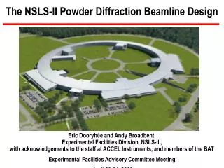
The NSLS-II Powder Diffraction Beamline Design. Eric Dooryh é e and Andy Broadbent, Experimental Facilities Division, NSLS-II , with acknowledgements to the staff at ACCEL Instruments, and members of the BAT Experimental Facilities Advisory Committee Meeting April 23-24, 2009. Outline.

The NSLS-II Powder Diffraction Beamline Design
E N D
Presentation Transcript
The NSLS-II Powder Diffraction Beamline Design Eric Dooryhée and Andy Broadbent,Experimental Facilities Division, NSLS-II , with acknowledgements to the staff at ACCEL Instruments, and members of the BAT Experimental Facilities Advisory Committee Meeting April 23-24, 2009
Outline Introduction to Eric Dooryhée (XPD Group Leader) Scientific Mission and Requirements (Eric Dooryhée) End Station Beamline Design Iteration (Andy Broadbent) Current Optical Layout Issues and conclusions
Eric Dooryhée • Past EmploymentJune 1st, 2009 NSLS II powder diffraction beamline2001-2008 senior scientist fellowship (Neel Institute, CNRS, FR)1996-2000 powder diffraction (ESRF BM16, now ID31)1990-1995 High energy ion and Laser Research Center (CNRS, FR)1988-1989 Post-doc powder diffraction (SRS Daresbury, UK) • Research • powder diffraction (SRS, ESRF, SOLEIL, neutrons ILL) • (in situ, line profile, direct space and Rietveld, upgrade of ESRF-BM02) • epitaxial thin films/multilayers of oxides (ferroelectric, relaxor, magnetic) • cultural heritage (chair of “SR in Art and Archaeology” + IUCr commission)
Scientific Mission Use the brightness of NSLS II flux demanding - high throughput - high time resolution high angle resolution (structure solving, microstructure) beam focusing down to ~50μm (high spatial resolution) Use the high energy spectrum of the damping wiggler sample environments (non-ambient, in-situ, in-operando) high Q (PDF) on simultaneously operating side branch access K-edge of heavy elements (contrast diffraction)
Scientific Domains • Complex materials • Many atoms, heterogeneity, size and defects, poor scatterer • Functional/real materials functioning: in-situ / in-operando studies • Materials change structure under synthesis/operational conditions, e.g. catalysts, H2 storage • Towards real working devices, e.g., ultra-thin dielectric films, fuel cell electrodes • Nanoscale materials • Bottom up design and build of materials with directed functionality • Hierarchical materials: control structure on different length-scales
First End Station Courtesy of SLS and ASP Rotation stage for high energy resolution crystal analysers, 1µradian resolution 10µradian accuracy. Standardized interface plate, supports 35kg at the sample position. Robot for automated sample changing (not shown). Custom Ge based strip detector with 100°coverage. 250µradian resolution on 0.5m radius. Support table for intermediate weight sample environments (~100kg)
High resolution (“multi-modal”) SLS (MS) 5ESRF (ID31) 9 (Ge to Si) (Hodeau et al. SPIE 1998)APS (11BM) 12ALBA 13 SOLEIL (CRISTAL) 21 DIAMOND (I11) 45 (5 banks of 9) • High energy Laue curved analyzer(see Zhong, Siddons, Hastings, Kao) Courtesy of Chiu Tang DIAMOND Off-plane diffraction analyzer (patent 2007)
High Energy Micro-Diffraction • many samples are inherently heterogeneous (multi-scale) • beam size should match : graininess, heterogeneity scale, sample geometry • variable focal spot size • imaging mode, micro-diffraction (~500 to ~50μm) • total crystallography: neither a powder nor a single crystal commercially available CRL set-up of Prof. Lengeler (Aachen)
Beamline Design Iteration • Due to extensive changes in scientific objectives ACCEL were commissioned to revise the design to concentrate on the higher energies. The changes requested use both commercial experience and unique in-house expertise, and can be made within the existing budget. • Active involvement of all members of the BAT in developing the beamline design. • 2nd Beamline Scientist interviews in progress.
Conceptual Beamline Layout in use at NSLS X17 and tested at X7bDr. Z. Zhong design
Damping Wiggler Power Management • Full 7m damping wiggler length (65kW). • Selective aperturing: • central part of the fan has higher energies, • restrict aperture to ~1mrad (H) x 0.1mrad (V), • still leaves almost 6kW! • Concentrating on the high energies allows extreme filtering: • multistage C (5mm total) and Al (8mm total) filtering leaves just 280W, of which 21W is absorbed in the 0.5mm Si crystal; • the cost is some loss of useful flux: • lose 64% of flux at 50 keV, and • lose 46% of flux at 80 keV.
Main Beamline Performance Vertical focusing (or collimation) with CRLs, dE/E~1x10-4, Si[311]
Second End Station (long set-ups) A key requirement of the User community is to provide for fast changeover of samples and environments. Typical experiments may include gas rigs, high-pressure, high or low temperatures....
Side-Branch Beamline Laue or Bragg single bounce mono (~4 degree deflection) with horizontal focusing, Vertical focusing with CRLs, Fixed energy at 80 keV, Energy resolution of ~4 x 10⁻³ allowable
Issues and Conclusions The only high-resolution instrument in the US capable of collecting data at high energies ( 40 keV to 100 keV) ideal for high-Q data and in situ and time resolved studies in environmental cells. Combining complementary analysis probes, e.g., micro-raman Investigation and development required on: beam filtering and DLCM : heat load, band pass,... deflecting side bounce monochromator (including cooling scheme) focusing : mono and CRLs Detector development e.g. Siddons’ work on Ge strip array Start work on software requirements and sample environments Conceptual design report due end Sept 2009.