State Machine Design Using State Machine Chart
110 likes | 132 Vues
Understand state machine chart components, blocks, rules, and conversion types for effective state machine design in hardware. Learn the construction, realization, and timing of state machine charts, parallel, serial forms, and equivalency with examples provided.

State Machine Design Using State Machine Chart
E N D
Presentation Transcript
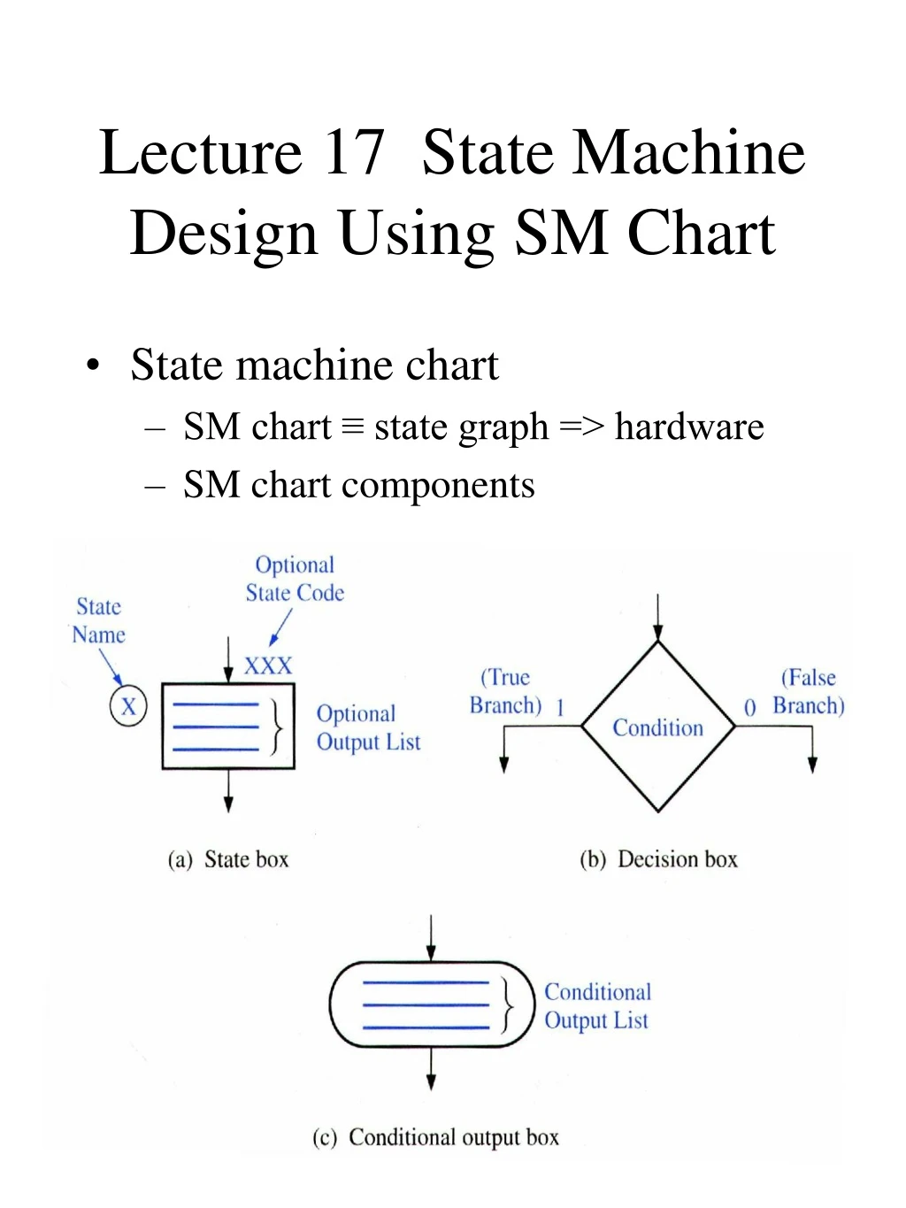
Lecture 17 State Machine Design Using SM Chart • State machine chart • SM chart ≡ state graph => hardware • SM chart components Chap 19
SM Chart Components • State machine chart • State box: state of the system • Output list, state code, state name • Decision box • Conditional output box. Output depends on the state of the system and inputs. Chap 19
SM Blocks • SM chart is constructed from SM blocks. • One state box, decision boxes, conditional output boxes. • Entrance(s) with several exit paths. • A SM block:machine operation in one state. • Outputs on the output lists of the state box become true. • Link path: path form entrance to exit Chap 19
SM Blocks • When state S1 is entered, output Z1 and Z2 = 1 • If input X1=0 and X2 = 0, Z3, and Z4 = 1. In this case, exit path = 1 at the end of the state time. Chap 19
Equivalent SM Blocks • Output Z2 = 1, if X1 = 0, • Next state S2 if X2 =0 and S3 if X2 = 1 Chap 19
S0/ S0/ Equivalent SM Charts for a combinational ckt. • Only one state, no state changes. • (b) equivalent SM chart. • Z1 = 1 if A + BC = 1, else Z1 = 0 • Z1 = 1 if A = 1 or if A = 0, B = 1,and C = 1 • Z1 = A + A’BC = A + BC Chap 19
SM Chart Construction Rules • Every valid combination of input variables must be exactly one exit path defined. • No internal feedback within an SM block is allowed. Chap 19
S0/ Parallel and Serial Form • Parallel form • More than one of the paths can be active. If X1 = X2 = 1 and X3 = 0, output Z1, Z2 and Z3 = 1 • Equivalent serial form. • All of the tasks take place within one clock time. Chap 19
Conversion • Moore output (Za, Zb, Zc). • Mealy output (Z1, Z2) • Input X Chap 19
Timing • Moore output (Za, Zb, Zc) • Mealy output (Z1, Z2) • Input X • State change on rising edge Chap 19
Realization of SM Charts • Moore output • In state 00, Za = A’B’, similarly, Zb = A’B, Zc = AB • Mealy output • Conditional output • Z1 = ABX’ • Z2 = ABX • Next state (terminated at A = 1, B = 1) • Find all the link paths that lead into the state with Q = 1 • B+ = A’B’X + A’BX + ABX • A+ = A’BX + ABX (link2 + link3) link 1 link 2 link 3 Chap 19