Bolt Failure
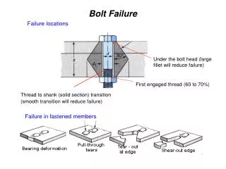
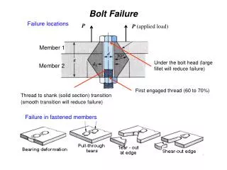
Under the bolt head (large fillet will reduce failure). First engaged thread (60 to 70%). Thread to shank (solid section) transition (smooth transition will reduce failure). Failure in fastened members. Bolt Failure. Failure locations. P. P (applied load). Member 1. Member 2.

Bolt Failure
E N D
Presentation Transcript
Under the bolt head (large fillet will reduce failure) First engaged thread(60 to 70%) Thread to shank (solid section) transition (smooth transition will reduce failure) Failure in fastened members Bolt Failure Failure locations P P (applied load) Member 1 Member 2
Snowmobile suspension bolt The picture shows the front ski suspension system for a snowmobile.The operator of the snowmobile was badlyinjured when the sled suddenly veered to one side, throwing him into a tree. The bolt failed in the threaded section at a shear point in the bracket. It is generally considered poor design to allow significant alternating shear or bending forces in the vicinity of the threaded section of the bolt since the threads form a stress riser and tend to initiate fatigue cracks, as happened in this case. A better design would be to utilize a bolt with a shorter threaded section so that the unthreaded shank material is at the shear area of the bracket. This eliminates the stress riser from the threaded section and increases the effective bolt diameter.
Boston's Big Dig tunnel, several tons of ceiling tiles fell and fatally crushed a motorist July 10, 2006
Heavy vehicle rollover collisions present special cases that often involve allegations of mechanical failure leading to rollover. In this specific case shown, the front axle u-bolt was alleged to have failed, causing the rollover. But, photo shows the fractured u-bolt which indicates a single point overload failure with zero evidence of slow crack propagation or fatigue.
Industry: Amusement Park360° Looping Ship Ride Problem: During the first two weeks of assembling a large new ride, large diameter bolts were breaking one to three days after they had been installed. This ride is essentially a large boat with seating for forty people. It is connected via steel structural members to a central pivot point, much like a very large swing set. Directly opposite the "ship," above the pivot point, there is a connecting metal structure with a massive counterweight attached. The bolts that were failing held the counterweight to the structural frame. The bolts are 1 1/4" x 10", SAE Grade 5. The fracture surfaces had a craggy, rock candy appearance. the most revealing test was core hardness. The readings were very low; in fact, when Rockwell hardness readings were made directly in the center of the bolt, there were so soft it was as if the bolts were never heat treated at all.
Industry: Amusement – Large ParkRoller Coaster Ride Problem: Hex socket shoulder screws, chosen as link pins between cars, were losing their heads. The remaining portions would then fall through the holes, causing the cars to separate. Ultimately, some of the cars would jump the track and then crash while carrying occupants. The machining process left small score lines in the area under the head. The score lines acted as stress risers that led to initiation of cracks under the violent forces of the ride. The cracks propagated until breakage, and the body of the screw dropped through. Aided by a hand-held magnifier, the fracture surfaces of the failed products appeared to be clearly fatigue related.
Industry: Amusement – Large ParkPeaceful Water Ride Attraction – On Tracks Problem: Bolts holding the wheels onto the axles were breaking at the head-to-shank juncture. The wheels would fall off, allowing the ride to float free. Some riders needed to be rescued by a boat and divers. The forces acting on the head-to-shank juncture of the bolts were unreasonable and excessive, as the bolt heads had to absorb the force and shock of all movement cause by passengers entering and exiting the ride.
The bolt securing this saddle to the seat post broke while the rider was cycling. The bolt may have been loose causing an increased bending load on the screw thread. This failure occurred only three months after purchase. The bolt's function is to fasten a clamp onto the saddle rails, this transmits the seat loads to the seat post (not represented on the picture). Because the lower part of the clamping system is serrated, it is not free to move if the bolt is only slightly loose. A bending moment is applied to the screw if the cyclist transfers their weight forward or backwards in the saddle. The geometry of the component loading therefore suggests that the failure might be caused by bending fatigue. These magnified views of the fracture surface show two zones that confirm the hypothesis of bending fatigue. The fatigued zone (left half of the image) seems to have several initiation points. The fatigue strength of this bolt is severely compromised by its threads. One possible improvement to its design would be to ensure that the part of the bolt that was likely to be exposed to bending stresses was not threaded.
This front brake assembly broke off under braking and severely injured the cyclist. Poor maintenance had allowed the brake bolt to loosen and allow the assembly to "chatter" when braking imposing cyclic loads instead of steady stress on the fastening bolt. As can be seen at higher magnification the failure was caused by bending fatigue in the steel brake mounting bolt which should be firmly secured through the cycle fork.
Description of accident The aircraft was taxiing along a grass runway prior to take-off when there was a loud cracking noise followed by the immediate collapse, in a forwards direction, of the left main landing gear. This caused the aircraft to slew to the left and resulted in the nose wheel striking the raised edge of an adjacent road. The pilot and passenger were uninjured, the aircraft sustained damage to the left wing tip, propeller and nose landing gear in addition to the left main landing gear. Description of landing gear The main landing gear leg is attached to the underside of the fuselage by means of three bolts as shown. A separate parts list within the assembly manual calls up three different bolts. In practice, each bolt may have to be individually selected to take account of variations in thickness of the fuselage underside. Of the three bolts, one had failed approximately 20 mm from the underside of the head and the remaining two were intact but bent. The geometry of the landing gear is such that the landing shock loads tend to deflect the legs forwards; this imparts the greatest stress on the rearmost of the outboard bolts and it was this one that failed. The examination revealed that the bolt failure had occurred as a result of a simple bending fatigue mechanism, with multiple initiation sites. There was evidence, in the form of a relative lack of smearing of the cadmium plating on the thrust face of the nut and the underside of the bolt head, which suggested that the assembly had not been fully tightened. This would have reduced the bolt's fatigue resistance. The condition of the forward outer bolt was the same, although the inboard bolt appeared to have been adequately tightened. It was noted that the threaded end of the inboard bolt contained at least three fatigue cracks in the thread roots. The result of investigation suggested that that one or more of the bolts may have been insufficiently tight, allowing movement of the gear leg within the clamp.