Chapter 8: Intake and Exhaust Systems
460 likes | 1.09k Vues
Air Cleaners. Originally, oil-bath air cleaners were utilized. Oil from cup at bottom of air cleaner was carried upwards into wire mess media where dirt was trapped in the oil.Newer dry-type air cleaners utilize swirling action to separate larger particles, paper element to trap smaller particle.

Chapter 8: Intake and Exhaust Systems
E N D
Presentation Transcript
1. Chapter 8: Intake and Exhaust Systems BAE 599 - Lecture 8
2. Air Cleaners Originally, oil-bath air cleaners were utilized. Oil from cup at bottom of air cleaner was carried upwards into wire mess media where dirt was trapped in the oil.
Newer dry-type air cleaners utilize swirling action to separate larger particles, paper element to trap smaller particle. Less that 0.5 Pa pressure drop across filter.
3. Fig. 8.1: Dry-Type Air Filter
4. Donaldson Powercore Air Filters
5. Donaldson Powercore Air Filters
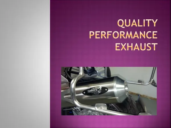
6. Mufflers Serve to reduce velocity of exhaust gases by increasing pressure.
Reduces noise levels.
Serves as a spark arrester � needed in high plant residue environments.
Two types: A) straight through, and B) reverse flow.
7. Fig. 8.4: Muffler Types
8. Supercharged Engines Superchargers compress intake air supply to engine � thereby enabling higher fueling rates and greater power production.
Superchargers can be either mechanically driven, or driven by the exhaust gases (turbocharger).
9. Fig. 8.5: Turbocharger Diagram
10. Air-Delivery Ratio Theoretical air consumption (4-cycle) can be written as,
where ra is the density of the air entering the compressor.
11. Air-Delivery Ratio The deliver ratio, ev, is,
where ma is the air consumption of the engine.
12. Air Delivery Ratio The Ideal Gas Law can also be utilized to estimate ev,
where the subscript 1 denotes the conditions of air entering the compressor, and 2, air exiting the compressor.
13. Fig. 8.6: Compressor Performance Map
14. Compressor Maps Efficiencies typically range between 0.5 and 0.8.
Maps include lines of constant compressor speed.
Surge line defines regions (to left) where turbo operation is unstable � surge is common.
15. Turbine Pressure Ratio The turbine pressure ratio, kpt, is defined as,
where the subscripts 3 and 4 denote exhaust gases entering and leaving the turbine, respectively.
16. Fig. 8.7: Turbine Performance Maps
17. Turbine vs. Compressor Flow Rates The turbine/compressor mass flow rate ration can be written as,
where the mass flow rate out of the engine (mt) is equal to the mass flow rates of fuel (mf) and air (mc) into the engine.
18. Selecting a Turbocharger for an Engine The pressure ratio across the compressor must first be defined as,
where the �boost� pressure is the pressure rise across the compressor.
19. Selecting a Turbocharger for an Engine The corresponding temperature ratio across the compressor can be estimated as,
where ec is the compressor efficiency.
20. Steps for Sizing a Turbo Select an achievable desired power output for the engine in question (pbme<1250 kPa).
Calculate the required fuel mass flow rate using a realistic BSFC value (0.20<BSFC<0.25 kg/kWh).
Determine the mass air flow rate (25<A/F<32 for CI engines).
21. Steps for Sizing a Turbo Select a compressor, and the point on the compressor map where the engine will operate at rated speed and power. Previous relationships can be utilized as an aid to finding this point,
This equation must be solved iteratively by assuming a value for ec, and then solving for kpc.
22. Steps for Sizing a Turbo Next, the compressor map is entered at values of ma and kpc, and ec is determined. If the ec from the solved equation does not match the ec on the compressor map, then the latter ec is used to solve for a new kpc, and the process is repeated.
Select a turbine and the operating point on the turbine map.
Remember, the compressor and turbine must operate at the same speed.
The turbine flow must match the compressor flow times (1+F/A).
Turbine must supply enough power to drive the compressor and to overcome bearing friction.
23. Turbocharger Mechanical Efficiency The turbocharger mechanical efficiency (em) can be estimated as,
where Cpc is the specific heat of ambient air at constant pressure while Cpt is the specific heat of heated air at constant pressure.
24. Turbocharger Mechanical Efficiency The previous equation can be reformulated as,
25. Comment on Process Turbine efficiencies are typically 0.98.
Values for Cpc, Cpt and k� must be obtained from a table where, the latter two are temperature dependent and should be selected in accordance with the exhaust temperature (T3).
tavailable must be greater than trequired or the turbine will not drive the compressor fast enough to develop the desired boost.
T3-T2 (temperature rise) across the engine is largely a function of F/A ratio � typically between 480 and 580 C.
26. Fig. 8.8: Characteristic Values of t
27. Example A turbocharger is to be fitted to a 10 L diesel engine, which is to run at 2400 rpm rate speed and provide a brake power of 180 kW. The density of ambient air is 1.16 kg/m3, the desired A/F ratio of the turbocharged engine is 30:1, and it is estimated the engine can achieve a BSFC of 0.25 kg/kWh.
28. Solution
29. Solution
30. Solution
31. Fig. 8.9: Turbocharger Operation
32. Operation Lubrication is critical to turbocharger life, start the engine and allow to run at low idle to insure bearings are properly lubricated.
Turbocharger lag occurs when fuel delivery is rapidly increased. There is a brief period of time when the turbocharger fails to extract enough energy to supply enough air (to match the proper A/F ratio) � resulting in transient black smoke (unburned fuel).
33. Altitude Compensation When engines are operated at higher altitudes the air is less dense, and therefore NA engines produce less power and must be de-rated in these applications.
Turbochargers tend to compensate for the lower density air as the pressure difference at the turbine is increased (higher turbine speeds) causing the compressor to push more air into the engine � de-rating is no longer required.
34. Intercoolers
35. Intercoolers Intercoolers cool the air between the compressor and intake manifold (15 to 20 C reduction).
Can be air-air or air-water (cooling system fluid).
36. Cooling Temperature changes can be approximated as,
where mai is the mass flow of engine air through the intercooler, and ms is the mass flow of cooling air.
37. Cooling The air-delivery ratio for a turbocharged and intercooled engine is estimated as,
where T2i is the air temperature after the intercooler.
38. Fig. 8.11: Temperature Variations in Air-Air Intercooler
39. Table 8.1: Engine Family
40. Homework Set No. 7 Do the odd problems at the end of Chapter 8 for next Tuesday.
41. NHRA diesel rail?
42. NHRA diesel rail?