Digital Communications: Pulse Digital Modulation
890 likes | 953 Vues
Pulse Digital Modulation: Elements of PCM; Sampling, quantization and coding; Quantization error, non-uniform quantization and companding<br>

Digital Communications: Pulse Digital Modulation
E N D
Presentation Transcript
PPTs ON DIGITAL COMMUNICATIONS (AECB20) III B.Tech(ECE) V semester (Autonomous R16) (2019-20) Department of Electronics & Communication Engineering By Dr. S China Venkateswarlu, Professor-ECE. E mail id: sonagiricv@gmail.com c.venkateswarlu@iare.ac.in
Pulse Digital Modulation Introduction Pulse Digital Modulation: Elements of PCM, quantization and coding Quantizationerror, non-uniformquantization and companding PCM: It is an analog to digital (A/D) transformation used in digital communication systems. It mainly belongs to the topic of quantization. Sampling Pulse-code modulation is a method used to digitally represent sampled analog signals. It is the standard form of digital audio in computers, compact discs, digital telephonyand other digital audio applications. In a PCM stream, the amplitude of the analog signal is sampled regularly at uniform intervals, and each sample is quantized to the nearest value within a range of digital steps.
Pulse Digital Modulation Introduction to Digital Communication : Data transmission, digital transmission, or digital communications is the physical transfer of data (a digital bit stream or a digitized analogue signal) over a point-to-point or point-to-multipoint communication channel. Ex: optical fibres, wireless channels, computer buses.... Pulse Modulation — Analog Pulse Modulation: PAM, PDM, PWM, PPM — Digital Pulse Modulation: PCM, DM, DPCM Quantization Process: Uniform; Nonuniform Pulse-code Modulation (PCM): sampling, Quantization, encoding Noise in PCM: Channel noise, Quantization noise Time-Division Multiplexing: T1, Digital Multiplexers: Delta-Modulation: Slope-overload, Granular noise, Delta-Sigma mod. Linear Predictor: Linear Adaptive prediction Differential Pulse-code Modulation (DPCM): Adaptive DPCM
PCM PCM (Pulse Code Modulation) is a standardized method used in the telephone network (POTS) to change an analog signal to a digital one. The analog signal is first sampled at a 8-kHz sampling rate. Then each sample is quantized into 1 of 256 levels and then encoded into digital eight-bit words. Pulse-code modulation (PCM) is a method used to digitally represent sampled analog signals. It is the standard form of digital audio in computers, compact discs, digital telephonyand other digital audio applications. In a PCM stream, the amplitude of the analog signal is sampled regularly at uniform intervals, and each sample is quantized to the nearest value within a range of digital steps. Dr.S.China Venkateswarlu, Professor-ECE, IARE- Hyderabad.
Course outcome / Topic learning outcome Course Outcome Name of the Topic covered Topic Learning Outcome Pulse Digital Modulation: Elements of PCM; Sampling, quantization and coding; Quantization error, non- uniform quantization companding Understand and analyze Digital Modulation: Elements of PCM; Sampling, quantization and coding; Quantization error, quantizationand companding the Pulse CO2 and non-uniform
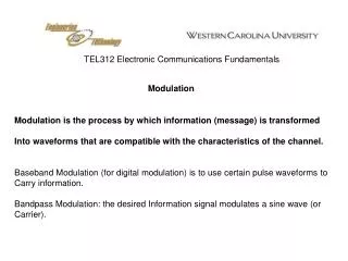
Pulse modulation Pulse modulation is a type of modulation in which the signal is transmitted in the form of pulses. It can be used to transmit analogue information. In pulse modulation, continuous signals are sampled at regular intervals. Pulse modulation can be classified into two major types. Analogue: Indication of sample amplitude is infinitely variable Digital: Indicates sample amplitude at the nearest predetermined level. A block diagram showing the basic classification of modulation techniques. Dr.S.China Venkateswarlu, Professor-ECE, IARE- Hyderabad.
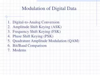
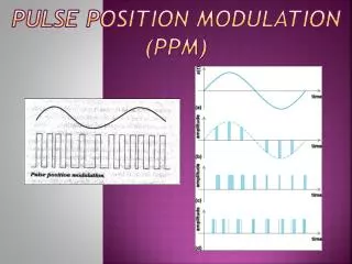
In CW modulation schemes some parameter of modulated wave varies continuously with message. In Analog pulse modulation some parameter of each pulse is modulated by a particular sample value of the message. Pulse modulation of two types 1. Analog Pulse Modulation : (i)Pulse Amplitude Modulation (PAM) (II)Pulse Train Modulation: a) Pulse width Modulation (PWM)/Pulse Division Modulation(PDM) b) Pulse Position Modulation (PPM) 2. Digital Pulse Modulation: (i) Pulse code Modulation (PCM) (ii) Delta Modulation (DM) Dr.S.China Venkateswarlu, Professor-ECE, IARE- Hyderabad.
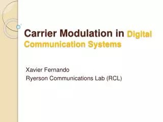
Pulse Code Modulation (PCM) Modulation is the process of varying one or more parameters of a carrier signal in accordance with the instantaneousvalues of the message signal. The message signal is the signal which is being transmitted for communication and the carrier signal is a high frequency signal which has no data, but is used for long distance transmission. There are many modulation techniques, which are classified according to the type of modulation employed. Of them all, the digital modulation technique used is Pulse Code Modulation (PCM). Dr.S.China Venkateswarlu, Professor-ECE, IARE- Hyderabad.
Modulations Modulations Dr.S.China Venkateswarlu, Professor-ECE, IARE- Hyderabad.
Pulse Code Modulation (PCM) This type of modulation is different from all modulations learnt so far. It is clear from the block diagram given at the top that it is a type of digital modulation.That is the signals here are sampled and sent in pulse form. A common feature among other techniques is that pulse code modulation also uses sampling technique. In this case, instead of sending a pulse train which is capable of continuously varying parameters, this type of generator produces a series of numbers or digits. Each digit in it represents the appropriate length of the sample at a particular instant. Basic block diagram of its realization is given below: Dr.S.China Venkateswarlu, Professor-ECE, IARE- Hyderabad.
Pulse Code Modulation (PCM) contd., Basic block diagram of its realisation is given below: Dr.S.China Venkateswarlu, Professor-ECE, IARE- Hyderabad.
Source: The source can be an analog signal. Example: A Sound signal Input Transducer: This is a transducer which takes a physical input and converts it to an electrical signal. (Example: microphone). This block also consists of an analog to digital converter where a digital signal is needed for further processes. A digital signal is generally represented by a binary sequence. Source Encoder: The source encoder compresses the data into minimum number of bits. This process helps in effective utilization of the bandwidth. It removes the redundant its unnecessary excess bits, i.e., zeroes unnecessary excess bits, i.e., zeroes. Channel Encoder: The channel encoder, does the coding for error correction. During the transmission of the signal, due to the noise in the channel, the signal may get altered and hence to avoid this, the channel encoder adds some redundant bits to the transmitted data. These are the error correcting bits. Dr.S.China Venkateswarlu, Professor-ECE, IARE- Hyderabad.
Digital Modulator: The signal to be transmitted is modulated here by a carrier. The signal is also converted to analog from the digital sequence, in order to make it travel through the channel or medium. Channel: The channel or a medium, allows the analog signal to transmit from the transmitter end to the receiver end. Digital Demodulator: This is the first step at the receiver end. The received signal is demodulated as well as converted again from analog to digital. The signal gets reconstructed here. Channel Decoder: The channel decoder, after detecting the sequence, does some error corrections. The distortions which might occur during the transmission, are corrected by adding some redundant bits. This addition of bits helps in the complete recovery of the original signal. Dr.S.China Venkateswarlu, Professor-ECE, IARE- Hyderabad.
Elements of PCM Dr.S.China Venkateswarlu, Professor-ECE, IARE- Hyderabad.
Elements of PCM Dr.S.China Venkateswarlu, Professor-ECE, IARE- Hyderabad.
Source Decoder: The resultant signal is once again digitized by sampling and quantizing so that the pure digital output is obtained without the loss of information.The source decoder recreates the source output. Output Transducer: This is the last block which converts the signal into the original physical form, which was at the input of the transmitter. It converts the electrical signal into physical output Example: loud speaker. Output Signal: This is the output which is produced after the whole process. Example − The sound signal received. Dr.S.China Venkateswarlu, Professor-ECE, IARE- Hyderabad.
Basic Elements of PCM Dr.S.China Venkateswarlu, Professor-ECE, IARE- Hyderabad.
Basic Elements of PCM The transmitter section of a Pulse Code Modulator circuit consists of Sampling, Quantizing and Encoding, which are performed in the analog-to-digital converter section. The low pass filter prior to sampling prevents aliasing of the message signal. The basic operations in the receiver section are regeneration of impaired signals, decoding, and reconstruction of the quantized pulse train. Following is the block diagram of PCM which represents the basic elements of both the transmitterand the receiver sections. Low Pass Filter: This filter eliminates the high frequency components present in the input analog signal which is greater than the highest frequency of the message signal, to avoid aliasing of the message signal. Dr.S.China Venkateswarlu, Professor-ECE, IARE- Hyderabad.
Sampler: This is the technique which helps to collect the sample data at instantaneous values of message signal, so as to reconstruct the original signal. The sampling rate must be greater than twice the highest frequency component W of the message signal, in accordance with the sampling theorem. Quantizer: Quantizing is a process of reducing the excessive bits and confining the data. The sampled output when given to Quantizer, reduces the redundant bits and compresses the value. Dr.S.China Venkateswarlu, Professor-ECE, IARE- Hyderabad.
Encoder: The digitization of analog signal is done by the encoder. It designates each quantized level by a binary code. The sampling done here is the sample-and-hold process. These three sections LPF, Sampler, and Quantizer LPF, Sampler, and Quantizer will act as an analog to digital converter. Encoding minimizes the bandwidth used. Regenerative Repeater: This section increases the signal strength. The output of the channel also has one regenerative repeater circuit, to compensate the signal loss and reconstruct the signal, and also to increase its strength. Dr.S.China Venkateswarlu, Professor-ECE, IARE- Hyderabad.
Decoder: The decoder circuit decodes the pulse coded waveform to reproduce the original signal. This circuit acts as the demodulator. Reconstruction Filter: After the digital-to-analog conversion is done by the regenerative circuit and the decoder, a low-pass filter is employed, called as the reconstruction filter to get back the original signal. Hence, the Pulse Code Modulator circuit digitizes the given analog signal, codes it and samples it, and then transmits it in an analog form. This whole process is repeated in a reverse pattern to obtain the original signal. Dr.S.China Venkateswarlu, Professor-ECE, IARE- Hyderabad.
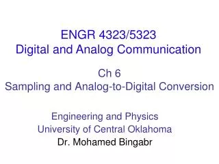
Sampling is defined as, “The process of measuring the instantaneous values of continuous-time signal in a discrete form.” Sample is a piece of data taken from the whole data which is continuous in the time domain. When a source generates an analog signal and if that has to be digitized, having 1s and 0s i.e., High or Low, the signal has to be discretized in time. This discretization of analog signal is called as Sampling. The following figure indicates a continuous-time signal x t and a sampled signal xst. When x t is multiplied by a periodic impulse train, the sampled signal xst is obtained Dr.S.China Venkateswarlu, Professor-ECE, IARE- Hyderabad.
Basic scheme of PCM system The most common technique for using digital signals to encode analog data is PCM. Example: To transfer analog voice signals off a local loop to digital end office within the phone system, one uses a codec. Because voice data limited to frequencies below 4000 Hz, a codec makes 8000 samples/sec. (i.e., 125 microsecond/sample). If a signal is sampled at regular intervals at a rate higher than twice the highest signal frequency, the samples contain all the information of the original signal. If a signal is sampled at regular intervals at a rate higher than twice the highest signal frequency, the samples contain all the information of the original signal (Proof - Stallings appendix 4A) Dr.S.China Venkateswarlu, Professor-ECE, IARE- Hyderabad.
Voice data limited to below 4000Hz Require 8000 sample per second Analog samples (Pulse Amplitude Modulation, PAM) Each sample assigned digital value 4 bit system gives 16 levels Quantized Quantizing error or noise Approximations mean it is impossible to recover original exactly 8 bit sample gives 256 levels Quality comparable with analog transmission 8000 samples per second of 8 bits each gives 64kbps Dr.S.China Venkateswarlu, Professor-ECE, IARE- Hyderabad.
PCM Block diagram Most common form of analog to digital modulation Four step process 1. Signal is sampled using PAM (Sample) 2. Integer values assigned to signal (PAM) 3. Values converted to binary (Quantized) 4. Signal is digitally encoded for transmission (Encoded) Dr.S.China Venkateswarlu, Professor-ECE, IARE- Hyderabad.
Steps Process Analog signal is sampled. Converted to discrete-time continuous-amplitude signal (Pulse Amplitude Modulation) Pulses are quantized and assigned a digital value. A 7-bit sample allows 128 quantizing levels. PCM uses non-linear encoding, i.e., amplitude spacing of levels is non-linear There is a greater number of quantizing steps for low amplitude This reduces overall signal distortion. This introduces quantizing error (or noise). PCM pulses are then encoded into a digital bit stream. 8000 samples/sec x 7 bits/sample = 56 Kbps for a single voice channel. Dr.S.China Venkateswarlu, Professor-ECE, IARE- Hyderabad.
Steps Process Dr.S.China Venkateswarlu, Professor-ECE, IARE- Hyderabad.
PCM Example Dr.S.China Venkateswarlu, Professor-ECE, IARE- Hyderabad.
Pulse Digital Modulation Dr.S.China Venkateswarlu, Professor-ECE, IARE- Hyderabad.
Sampling sampling is the reduction of a continuous-time signal to a discrete-time signal. A common example is the conversion of a sound wave (a continuous signal) to a sequence of samples (a discrete-time signal). A sample is a value or set of values at a point in time and/or space. A sampler is a subsystem or operation that extracts samples from a continuous signal. A theoretical ideal sampler produces samples equivalent to the instantaneous value of the continuous signal at the desired points. The original signal is retrievable from a sequence of samples, up to the Nyquist limit, by passing the sequence of samples through a type of low pass filter called a reconstruction filter. Dr.S.China Venkateswarlu, Professor-ECE, IARE- Hyderabad.
Signal sampling representation. Signal sampling representation. The continuous signal is represented with a green colored line while the discrete samples are indicated by the blue vertical lines. Sampling can be done for functions varying in space, time, or any other dimension, and similarresults are obtainedin two or more dimensions. For functions that vary with time, let s(t) be a continuous function (or "signal") to be sampled, and let sampling be performed by measuring the value of the continuous function every T seconds, which is called the sampling interval or the sampling period. Then the sampled function is given by the sequence: s(nT), for integer values of n. The sampling frequency or sampling rate, fs, is the average number of samples obtainedin one second (samplesper second), thus fs= 1/T.
Sampling process Dr.S.China Venkateswarlu, Professor-ECE, IARE- Hyderabad.
A signal is pulse code modulated to convert its analog information into a binary sequence, i.e., 1s and 0s. The output of a PCM will resemble a binary sequence. The following figure shows an example of PCM output with respect to instantaneous values of a given sine wave. Instead of a pulse train, PCM produces a series of numbers or digits, and hence this process is called as digital. Each one of these digits, though in binary code, represent the approximate amplitude of the signal sample at that instant. In Pulse Code Modulation, the message signal is represented by a sequence of coded pulses. This message signal is achieved by representing the signal in discrete form in both time and amplitude.
The PCM system Two basic operations in the conversion of analog signal into the digital is time . discretization and amplitude discretization. In the context of PCM, the former is accomplished with the sampling operation and the latter by means of quantization. In addition, PCM involves another step, namely, conversion of quantized amplitudes into a sequence of simpler pulse patterns (usually binary), generally called as code words. (The word code in pulse code modulation refers to the fact that every quantized sample is converted to an R -bit code word.) Dr.S.China Venkateswarlu, Professor-ECE, IARE- Hyderabad.
The PCM system Dr.S.China Venkateswarlu, Professor-ECE, IARE- Hyderabad.
Sampling Rate To discretize the signals, the gap between the samples should be fixed. That gap can be termed as a sampling period Ts. Sampling Frequency=1/Ts=fs Where, Ts is the sampling time fs is the sampling frequency or the sampling rate Sampling frequency is the reciprocal of the sampling period. This sampling frequency, can be simply called as Sampling rate. The sampling rate denotes the number of samples taken per second, or for a finite set of values. For an analog signal to be reconstructed from the digitized signal, the sampling rate should be highly considered. The rate of sampling should be such that the data in the message signal should neither be lost nor it should get over-lapped. Hence, a rate was fixed for this, called as Nyquist rate. Dr.S.China Venkateswarlu, Professor-ECE, IARE- Hyderabad.
Nyquist Rate: Suppose that a signal is band-limited with no frequency components higher than W Hertz. That means, W is the highest frequency. For such a signal, for effective reproduction of the original signal, the sampling rate should be twice the highest frequency. Which means, fS=2W fS=2W Where, fSfS is the sampling rate W is the highest frequency This rate of sampling is called as Nyquist rate. A theorem called, Sampling Theorem, was stated on the theory of this Nyquist rate. Dr.S.China Venkateswarlu, Professor-ECE, IARE- Hyderabad.
Quantization Quantization is the process of mapping continuous infinite values to a smaller set of discrete finite values. In the context of simulation and embedded computing, it is about approximating real-world values with a digital representation that introduces limits on the precision and range of a value. Quantization is the process of constraining an input from a continuous or otherwise large set of values (such as the real numbers) to a discrete set (such as the integers). The terms quantization and discretization are often denotatively synonymous but not always connotatively interchangeable. Dr.S.China Venkateswarlu, Professor-ECE, IARE- Hyderabad.
Quantization contd. The process of converting an infinite number of possibilities to a finite number of conditions. Analog signals contain an infinite number of amplitude possibilities Thus, converting an analog signal to a PCM code with a limited number of combinations requires quantization @ the process of rounding off the amplitudes of flat-top samples to a manageable number of levels Example: A sine wave with a peak amplitude of 5 V varies between +5 V and -5 V passing through every possible amplitude in between. A PCM code could have only 8 bits which equates to only 28or 256 combinations. Obviously to convert samples of a sine wave to PCM requires some rounding off. Dr.S.China Venkateswarlu, Professor-ECE, IARE- Hyderabad.
Quantization example:3-bit PCM code Dr.S.China Venkateswarlu, Professor-ECE, IARE- Hyderabad.
Analog input signal Sample pulse PAM signal PCM code Dr.S.China Venkateswarlu, Professor-ECE, IARE- Hyderabad.