Download
1 / 13
160 likes | 831 Vues
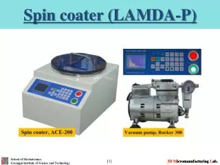
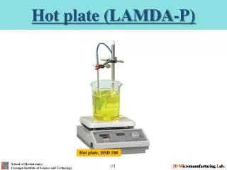
Hot plate (LAMDA-P). What is the hot plate and features?. After uniform thin films coated, the liquid solution is necessary to be solidified. At this moment, hot plate is used to solidify the solution.

E N D
What is the hot plate and features? • After uniform thin films coated, the liquid solution is necessary to be solidified. • At this moment, hot plate is used to solidify the solution. • The temperature is accurately controlled by a temperature controller that uses digital PID auto-tuning function, setting and real temperature can be simultaneously confirmed. • Temperature controller built-in timer function. • Ceramic coated top plate has rapid thermal conductivity and very uniformly maintain the surface temperature. • Stirring speed is maintained constant speed by feedback control.
Each part designation and description Measurement unit display (PV): The current temperature during control and the various parameters during setting are displayed respectively. Setting unit display (SV): The setting temperature during control and each parameter value during parameters setting are displayed respectively. While the timer is operated by pressing 9 ( ) button for a few sec., remaining time is displayed with blinking. Control output indicator lamp (OUT): The light is on, after starting control output. Upper and lower limit alarm indicator lamp (ALM): When set upper and lower limit alarm is activated, the lamp is turned on.
Each part designation and description cont. Auto-tuning operation indicator lamp (AT): When PID auto-tuning (automatic operation) is started by pressing 11 ( ) button, the current operation state is displayed with turning on the lamp. After finishing operation, the lamp is turned off. Timer operation lamp: When the timer is on by pressing 10 ( ) button, the operating timer is displayed with blinking. After the set time is over, the lamp is turned off and “tENd” is displayed on setting unit display (SV). LBA operation lamp: When the control loop break alarm is occurred, the lamp is turned on. Mode setting button: If pressing button for more than 2 sec., PV and SV are changed parameter setting mode. This button is also used to switch each parameter.
Each part designation and description cont. Decreasing setting value button (remaining time display button): The setting value is decreased one by one with pressing button. If pressing button for more than 2 sec., the value is continuously decreased. While the timer is operated by pressing button for a few sec. in controlling state, remaining time is displayed with blinking. Increasing setting value button (timer on/off button): The setting value is increased one by one with pressing button. If pressing button for more than 2 sec., the value is continuously increased. If pressing button for a few sec. during controlling state, the timer can be on/off. After the timer is over, “tENd” is displayed on setting unit display (SV). If pressing button for a few sec. again, returning to initial state.
Each part designation and description cont. Auto-tuning button: After setting parameters, if pressing button for more than 2 sec., operating the optimum PID integer automatically with turning on auto-tuning operation indicator lamp (AT).
Parameters setting method cont. After all parameters are set, button is pressed for more than 2 sec. to escape the parameter setting state. At this moment, the current and setting temperature are displayed at measurement unit display (PV) and setting unit display (SV) respectively and the control is started. If pressing button for more than 2 sec., the controller runs optimum control to operate automatically the most proper PID integer to the thermal properties of the actuator controller. If there is no any button operation for more than about 60 sec., returning to the initial state. At this moment, the previous parameter value is stored, not set parameter value.
Instruction to control the temperature ① After designating external sensor operation by # 16 button, insert sensor connector at # 17. (When using external sensor) ② Designate internal sensor operation. (When using internal sensor) After connecting cable to # 15, turn on the power switch of # 14. If pressing # 8 button for about 2 sec., the parameter of temperature setting is displayed. The expectative temperature is defined by pressing # 9 and 10 buttons. If pressing # 8 button for a few sec. after setting the temperature, the temperature controller is operated. (initial state)
Instruction to operate the timer The parameter of temperature setting is displayed with pressing # 8 button for a few sec.. If pressing # 8 button again, “tlm” is displayed. The expectative time is defined by pressing # 9 and 10 buttons. Minimum 1 min. (0001) ~ maximum 99 hr. 59 min. (9959) If pressing # 8 button for a few sec. after timer setting, returning to initial state. When operating the timer, press # 10 button for about 2 sec.. At this moment, the lamp of # 6 is blinked. If the timer is not set, not operating. If pressing # 10 button for about 2 sec. while the timer is operating, operation is stopped. If pressing # 9 button for about 2 sec. while the timer is operating, remaining time is displayed. At this moment, if pressing # 9 button for a few sec. again, the setting temperature is displayed. When the timer is over, “tENd” is displayed. If returning to initial state, press # 10 button for a few sec.
Instruction to operate the auto-tuning Because this PID Temp. Controller have already calculated PID values by experiment, it can be used without additional auto-tuning. If the temperature difference occurs a lot, auto-tuning is recommended. Auto-tuning is started by pressing # 11 button and the lamp of # 5 is blinked. Although there are some temperature errors during auto-tuning, the exact temperature is activated after auto-tuning is over. When using the thermostat, the temperature is firstly increased more than the set temperature but returned to normal state after a while. (Overshoot phenomenon)
Instruction to operate the motor • The expectant speed (# 12 display) is defined by rotating # 13 volume. • The speed can be controlled from 100 to 1500 rpm by adjusting volume. (The speed is increased by clockwise rotating # 13 volume or decreased by anticlockwise rotating # 13 volume in 10 rpm step.) • If anticlockwise rotating # 13 volume fully, the operation is stopped. • If rpm is set by rotating # 13 volume, the speed is reached to the setting rpm within a few sec.. The speed is maintained by the operation from the arrival time. • If the motor is not immediately rotated due to the influence of the load at first operation, the output should be quickly increased up to above 10 rpm to rotate the motor within 3 sec..